ESMD Course Material : Fundamentals of Lunar and
Systems Engineering for Senior Project Teams, with Application to a
Lunar Excavator
Contact: David Beale, dbeale@eng.auburn.edu
Contact: David Beale, dbeale@eng.auburn.edu
|
|
Chapter 3 Systems Engineering Example of a Cube Satelliteby David Beale and Joseph Bonometti
Contents The Systems Engineering (SE) method explained in Chapter 2 is demonstrated by the design of a cubic satellite ("cubesat") named the AS-1, as was performed by a student team. The cubesat is a complex multidisciplinary project with each subsystem being designed by a team of a particular discipline suited to that subsystem. This example is intended to present an example of the steps in the SE process, with comments presented in italics. The full report (AUSSP, 2007) describes the design of cubesat AS-1, and can be found at http://space.auburn.edu/page_attachments/0000/0046/Spring_2008.pdf (although the document is periodically being updated as the project progresses). Pre-Phase A and Phase A were completed, and the project is well on its way through Phase B with a baseline design and some detailed designs documentation. The eleven SE functions are applied in each phase, that includes the five around the triangle and the other six SE functions. Excerpts of the report were used to create this streamlined example. SE tools (e.g. block diagrams; mass, power, cost and link budgeting; trade studies; and failure mode analysis) were applied to SE functions when warranted. The report is periodically updated as the team progresses toward an operable system.
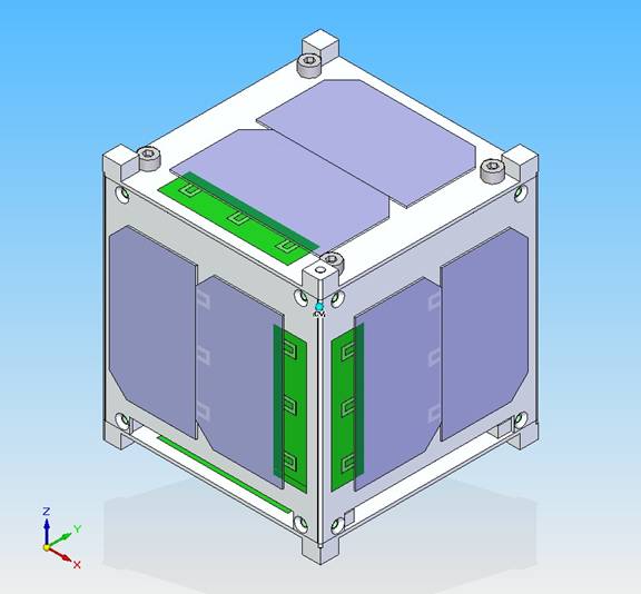
2‑1 Cubesat Structure, aluminum housing with solar panels (grey)
Project
Overview
The CubeSat Project began as a collaborative effort between
California Polytechnic State University San Luis Obispo and The mission objective for this student team is to test a GaN-based Ultraviolet (UV) photodetector in space. The student team was tasked to design, build and operate a CubeSat in Low Earth Orbit (LEO) carrying the photodetector as the payload. The cube structure is an enclosed aluminum box with solar cells clamped on the outside walls. Antennas are deployed perpendicular to the faces at the corners. Internals include sensors, a camera and printed circuit boards.
The launch is currently planned to be
onboard a Russian
Dnepr rocket from The team has made a report (AUSSP, 2007). The satellite system is not finished, the project is currently in Phase B: Preliminary Design and Technology Completion. Hierarchy of management and division of responsibilities was first established and duties assigned. The program manager is, in this case, the faculty advisor. The project manager is responsible for scheduling the development cycle, defining mission requirements and goals, as well as the overall success of the project. He is also responsible for keeping the project costs within budget. The systems engineer is responsible for guiding the engineering of the project; for defining, verifying and validating system requirements’ flow down to each subsystem; and for the integration and test phases of the project. He/she is also responsible for coordinating system trade studies, managing critical resources/interfaces for each subsystem and failure mode and risk analysis. Each subsystem lead is responsible for the development and testing of their individual subsystem, and must remain aware of how changes in their subsystem affect other subsystems and the system as a whole. The subsystem leads were selected in anticipation of the probable subsystems, i.e. payload, C&DH (Command and Data Handling), COMM (Communications), EPS (Electrical Power System), ADC (Attitude Determination and Control), Structures and Mechanisms, Thermal and Ground Station.
2‑2 Management structure. The bottom most level are the subsystem team leads and team members of that subsystem.
Systems Engineering Team and Subsystems Teams Responsibilities
Systems Engineering Team – Works for the systems engineer and may be a team of subsystem leads. Responsible for the 11 systems engineering functions. Analyzes the characteristics of the mission such as orbit and environment. Ensure all subsystems interface properly and work as one fully integrated satellite. Guide the systems engineering of the satellite, ensuring that all mission requirements are met, while bridging the various engineering disciplines. They manages mass and volume budget and oversees all other budgets except cost. They maintain a timeline of events (ConOps), mission profile and anomaly (abort, reboot, reduced operations, end of life, etc.) procedures. Ground Station Team – Designs, builds, and operates ground station antennas, mounting, enclosure, and computer. Selects and installs operating programs and data processing. Handles communication with AS-1 and tracking of other amateur satellites. Communications Team – Designs, builds, tests the onboard communication system including antennas, transceivers and TNCs. Manages the link budget. Attitude Determination and Control Team– Designs, builds and tests the ADC subsystem to achieve solar cell orientation to the sun for the EPS, and antenna orientation for communication. The subsystem includes magnets, hysteresis dampeners, and an attitude determination algorithm for a desired solar cell orientation. Command and Data Handling Team – Designs the command and data architecture. Selects hardware components, designs circuit board layout and programs the processor. Selects sensors and incorporates them into the design. Manages the data budget. Electrical Power System Team – Designs, builds and tests the power subsystem, including solar cells, rechargeable batteries and power regulators. Manages the power budget. Structures Team - Designs and builds the structure of the satellite, including the mountings for all components, fulfilling compliance with CubeSat specs and system requirements, including launch vibration. Oversees the vibration and load testing. Thermal Team – Conducts the steady-state and transient thermal analysis of both the internal and external structure to ensure component thermal requirements are met. Oversees the thermal vacuum testing and maintains the thermal budget and temperature range for all subsystems. Payload Team – Develops hardware components needed to accompany payload and ensures the design meets requirements set by the scientists. Oversees the payload functions testing. After recruitment operations are completed, the new student team - with guidance from the program manager and the project manager - works as a group to refine the goals, setting milestones with deliverables. Next, the team defines the requirements of the system and the subsystems. Subsystem leads, students who are designated by management to oversee each subsystem, play an important role in this process. Because Subsystem Leaders have usually been involved in the project for multiple semesters, they serve as a resource for new students and are able to share what works and what doesn’t from their experience. During the next series of exercises, the team develops a work breakdown structure (WBS) which is a list of activities that must be performed to reach their subsystem goals by the end of the semester. This clarifies in the students’ minds what work is done by each subsystem team. At this juncture, they are ready to choose which subsystem team to join. A responsibility matrix is established for each student and is signed by the student, the project manager and the program manager. All subsystems then work together to create a network diagram schedule. Finally a Gantt chart project schedule, is made and used as a guide and a tool for assessing progress and for assigning deadlines throughout the semester. The process of incorporating project management continues once the technical work has begun. During a short session at the beginning of each meeting, subsystem members are asked to communicate to the entire group what work has been done, what problems are being encountered, and what effect their status will have on the overall project schedule. These sessions allow a forum for problem solving as well as a reinforcement to students that they are accountable to the team. Additional daily assignments may be made to individual students by management in an effort to ensure preparedness for work in the lab. Students will participate in several design reviews throughout the semester. Reviews require students to create and give a presentation to the group and invited guests. All students are required to keep daily documentation of their work on AS-1 and are required to properly update their subsystem’s portion of the AS-1 Manual to reflect their contributions to the semester’s work. All student-produced documents and results are overseen by subsystem leads and management to ensure proper progress is being made. Leaders then work with students to overcome obstacles and complete projects. The systems engineering process is now demonstrated. The steps of Chapter 2 are followed in this example, starting with Pre-Phase A, going onto Phase A and Phase B. In each Phase some of the 11 SE functions are applied. Figures 2-3 and 2-4 are included to guide the process. The demonstration is by no means comprehensive. And often it is difficult to determine whether a particular team's action should have occurred in one particular phase, or more appropriately in another. The ideal approach is to not allow the details of the "process" to become a burden or the end goal in itself, but rather treat the process as a useful tool, being somewhat flexible and not rigid, and forge ahead with the work's true objective: producing the best functional satellite design.
KEY: Instructions are in regular font red
Comments are in unbold italics (except for headings)
2‑3 The System Engineering Functions, including the iterated functions shown around the triangle
2‑4 The project life-cycle as a Vee chart (R/A/C are the Requirements, Architectural Design and ConOps steps of Figure 6, SAITL is System Assembly, Integration, Test and Launch) Concept Studies (NASA Pre-Phase A)
Purpose: The
purpose of Pre-Phase A is to produce a broad spectrum of ideas and
alternatives (i.e. concepts) for the mission. The
focus is on the mission, specifically mission architecture, mission
requirements, and mission operation.
Systems Engineer's Tasks: Leads
all Pre-phase A activities with support from subsystems lead
personnel. Begin
documentation process. 11 Systems Engineering FunctionsInput The mission needs, which come as a mission statement and/or mission objectives, come from the project sponsor. The team should make sure the sponsor’s needs are understood as well as those of all other stakeholders.
Comment: In
this case the mission objective came from NASA and a professor, as a
challenge to the students. The
team believed that they could build a satellite, however they
wondered how they could get it into orbit on a small university
budget. Here
is where they tried to do their first trade study; they considered
other methods of launching, but none were found. An
investigation led them to the cubesat program and cubesat
requirements. The
GaN-based Ultraviolet photodetector is considered the payload.
Architecture and Design Development Visualize highest level systems and interfaces. List the functions that must be performed. Consider several strawman architectures. Put in block diagram form. For example, the Shuttle Transportation System consisting of option 1) orbiter, solid boosters and external tank or option 2) orbiter, solid boosters and two external tanks.
Architecture and Design: The
mission elements and interfaces will consist of the cubesat
satellite (with scientific payload), ground station and rocket. These
three subsystems are called the tier 1 systems. The
entire system will be called the cube satellite system or cubesat
system (CSS).
Interfaces: The payload
(GaN sensor) is interfaced to the satellite. The
satellite sends data wirelessly to the ground station. A
deployer (P-Pod) on the rocket will store and then launch the
cubesat.
2-5. Cubesat system through tier 1 systems.
In most cases there will be more
than one architecture, but this team was constrained by the CubeSat
requirements. Next
the team considered how it would operate. The
Operations Concept describes how the system will operate.
Concept of Operations (ConOps) The events which ensue from the moment the system is deployed, shown on a time scale and/or as sequence of events. The Operations Concept is initially developed as a draft concept during Pre-phase A, with refinement throughout the lifecycle, until the flight operations plan is completed in Phase D.
Concept of Operations
(ConOps): The cubesat will ascend to orbit on the rocket housed
inside the P-Pod deployer, be deployed into space, signal the ground
station to start mission operations, perform systems check, acquire
sensor data and transmit it back to earth. Derived Requirements Development
The mission statement/objectives are worked to mission requirements. The systems
engineer leads this activity with strong support from subsystem
personnel. Requirements
are often written as “shall” statements.
The mission shall be in
accordance with the CubeSat Design Specifications.
The satellite shall be
capable of being launched from a Russian DNEPR rocket going to LEO.
Validate and Verify
Check that the architecture, ConOps
and requirements are mutually consistent, and mission statement and
needs are met. Show
that the right system designs have been chosen. Develop
a validation plan to measure performance based on mission
requirements.
Validation Plan: In
Phase D, the cubesat system will be validated by performing a dry
run mission on earth, beginning with a mock deployment from a P-Pod,
and with the ground station as operations center.
Other SE Functions
Begin SEMP, begin assigning
responsibilities. Document
results of the systems engineering functions in a report and present
at MCR (Mission Concept Review). Create
an electronic library. Documents stored in the
electronic library should include: ConOps, Architecture and Design,
Requirements, Resources Budgets, trade studies.
Orbital Analysis
Analysis was performed using Satellite
Tool Kit (STK) from data available from Celestrack for other
university CubeSats. The typical CubeSat orbit has the following
characteristics:
Inclination: 98°
Altitude: 650 – 800 km
The RAAn is formulated specifically to
give the satellite a nearly constant-sun, sun synchronous orbit. The
orbital plane proceeds through the year to maintain this
constant-sun feature. This orbit is also almost polar, allowing
ground stations at any location on Earth to communicate with the
satellite at some point in time.
Environmental Analysis
The Exosphere
At 650 – 800 km altitude, the exospheric
mass density is between 10-14 and
10-15 kg/m3. The temperature ranges between
750K and 1000K, but the low density means there is essentially no
heat capacity, and no conductive heat transfer.
Molecular oxygen is
severely depleted at this altitude
because its bonds are easily broken by the incident UV radiation. In
this vacuum, tin-plated parts may 'whisker' causing short circuits.
The suggested mitigation is a conformal coating.
Plasma
In plasma, with a negatively-grounded
electrical system such as AS-1, the exposed charged areas, such as
solar cell contacts, can cause plasma arcing. This is usually only
severe in high-voltage arrays, such as the International Space
Station, which has more than 100V on the solar panels. The arcing
may be dissipated by a Zener diode and low-resistance,
high-power dissipation resistor.
Radiation
AS-1 orbit will take it through the VanAllen radiation belt's South
Atlantic Anomaly and the outer electron belt at high latitudes.
AS-1's 1.5mm aluminum shielding
will cut out electrons below 1MeV, and protons below 10MeV. The
remaining flux sums to 1 or 2 rads/day. With COTS parts life
expectancy at 2krads, AS-1's electronics should avoid TID damage for
about 10 years. The solar cells, however, have no shielding, and
will experience a dose rate of about 2x10³ rads(Si)/day. Because
our Improved Triple Junction cells use InP2 and GaAs, they have
increased radiation hardness over Si systems. The manufacturer
specifies that the cells will function at 88% of power after
receiving 5x10¹⁴ 1MeV/cm2 flux.
This corresponds to about 107 rads, which should take about 10,000
days, significantly longer than the batteries will last.
Micrometeoroid/Orbital Debris
Micrometeoroids are small, naturally
occurring, particles that may impact the spacecraft. The
distribution of their size and energy is statistical, but lower
nearer the atmosphere, where they tend to re-enter. It is assumed
that for a short duration mission, such as AS-1, micrometeoroids
will not be a significant cause of failure, and
that if they were, not much could be done
within our budget to prevent it. Orbital Debris is debris from
man-made sources, such as rocket explosive bolts, or entire
nonfunctional satellites. Orbital Debris tends to be worse in
popular orbits. A detailed analysis has not yet been performed on
the probability of impact micro-meteoroids or orbital debris. Concept and Technology Development (NASA Phase A)The effort now focuses the attention on the cubesat satellite itself, since the deployer and rocket exist. Purpose: The purpose of Phase A is to determine the feasibility and desirability of a system and establish a single approach and baseline system architecture. (A baseline is a set of documents (drawings, schematics, requirements) that will have changes controlled thru a formal approval process.) Just as the focus of Pre-Phase A was on the mission and mission requirements, this focus in Phase A is to produce system level requirements and a system level architecture. Here the team drives down the mission requirements to detailed system specification requirements, such as power voltage levels (i.e. 28 VDC +/- .5 V). Trade studies are performed to determine the best system for the project (remember that most likely more than one approach was produced in Pre-Phase A) , consider the key parameters, i.e. power consumption, weight, volume, space legacy, costs, etc. to choose the best approach. Propose the subsystems and anticipated performance of each, identify major components of the subsystems. Develop surrogate subsystem modes and run a trade space analysis of the alternatives. If necessary apply modeling techniques such as engineering modeling, state machines, block diagrams, computer simulations, proof-of-concept prototypes, mental models, or strawman designs to compare alternative architectures to home-in on the best. Identify risks and perform necessary analyses. System requirements, specifications and schematics are released in formal documents. Subsystem budgets are allocated and controlled from this point in time.
Systems Engineer's Tasks: Leads
all Phase A activities with support from subsystems lead personnel. 11 Systems Engineering FunctionsInput The input is the output of Pre-Phase A, which includes one or more high level system architectures, plus mission requirements and mission ConOps.
Architecture and Design Development Block diagram the system and its subsystems. List the functions that must be performed by each subsystem and anticipated performance.
The team now had enough
information to visualize the next tier systems (or subsystems) that
would be required to meet the requirements and operations concept,
so it develops a Product Breakdown Structure for the Cube Satellite
System or Cubesat System (CSS) to Tier 2 as shown below in Figure
2-5:
CSS Systems (Tier 1)
· The
ground station system for sending and receiving signals and
processing data from the cubesat satellite.
· The
rocket system, which includes Tier 1 systems:
o The
rocket
o The
deployer
· For the cube satellite system, which contains Tier 2 subsystems:
o A communications
system will be needed
to send signals from the satellite to the ground station.
o A command
and data handling system for
circuit boards, programming and selection of hardware for the
circuit boards.
o An electrical
power system with a
power supply and power regulators.
o A mechanisms
and structures system for
satellite cube, mountings and mechanisms for antenna and antenna
deployment.
o A thermal
system to ensure that
component temperature limits are not exceeded.
o An attitude
determination and control system for
satellite position and orientation sensing and adjustment.
o A payload
system to collect and
store voltage signals from the sensor.
Students on the C&DH team
visualized the components for their system:
C&DH Subsystem (Tier 2):
A microcontroller, a flash drive (perhaps 32 or 64 MB), a PC Bus,
analog to digital converter and general purpose input/output.
Figure 2‑5 Architecture of the Cube Satellite
Mechanical Interfaces: Launch
vehicle, and cubesat deployer (P-pod) are elements (systems) that
interface with the cubesat. Neither
the rocket nor the cubesat launcher will be designed here.
Electrical Interfaces: C&DH interfaces to
all systems, Power additionally interfaces to COMM, COMM interfaces
to Ground Station, and payload interfaces to C&DH.
Components were visualized and listed (without detailed
manufactures specifications) 2‑1: Table of subsystem major components
The events, which ensue from the moment the system is deployed, are to be shown on a time scale and/or as sequence of events that are updated to reflect Phase A activities.
Launch sequence –
This is a one time “sequence” preformed after launch. Once this
sequence is performed the satellite will only operate in one of the
four modes of operation (safe, idle, normal, and transmit).
Safe mode –
C&DH is on and ready to go into idle mode. Perform basic tasks, such
as battery charging, checking vital housekeeping.
Idle mode –
Only housekeeping electronics are on. C&DH is storing housekeeping
information. Batteries will also be charging if need be. Check
transmitting beacon.
Normal mode –
Science experiment running, C&DH will be storing data from
experiment. C&DH is collecting housekeeping data.
Transmit mode –
retrieve and transmit stored data, transmitting beacon, upload data
(transmitter shutdown, etc). Derived Requirements Development
System requirements can often be
written as "shall" statements. For
example, "The thermal system shall be capable of maintaining all
critical components within their operational temperature range".
"Power System voltage level shall be 28V +/- .5V". Establish
preliminary budgets for subsystems (power, data rates, RF links,
mass properties, etc.)
- Spacecraft Envelope Requirement – this is
typically dictated by the launch vehicle
-
Weight Requirement - this is typically dictated by the launch vehicle
-
Environmental requirements
-
Vibration and acoustics requirements are dictated by the launch vehicle
- Temperature and vacuum requirements – determined
by the planned mission.
- Determination of location
parameters based on science requirements and engineering needs
(i.e., solar panel orientation, thermal parameters)
- Establish preliminary budgets for
subsystems with a requirement on maximum resource utilization (e.g. power, data rates, RF links, mass properties, etc.)
Cubesat Satellite
Requirements:
· The
spacecraft must be capable of being launched from a Russian launch
site (i.e., Russian technical requirements and ITAR restrictions all
being met), going to LEO (i.e., environmental requirements being
net), and following all cubesat calpoly PPOD depolyer and cubesat
design requirements.
· AS-I
shall be designed for low earth orbit (LEO), 600-800km, 98°
inclination
· AS-I
shall conform to FCC regulations
· AS-I
shall not exceed a mass of 1kg
· AS-I
shall have no electronics active during launch
· AS-I
shall be capable of surviving the transit, pre-launch, launch, and
space environments. · Full system and subsystem level documentation shall be provided prior to integration of AS-I
· AS-I
shall conform to all CalPoly cubesat constraints and requirements.
Validate and Verify
Check that the architecture, ConOps
and requirements are mutually consistent, and mission statement and
needs are met. Strive
to show that the one right system design has been chosen, through
trade studies, performance analysis, modeling, etc.
Other SE Functions
Update SEMP. Document
results of the systems engineering functions in a report and present
at MDR (Mission Definition Review). Documents
updated in the electronic library should include the ConOps,
Architecture and Design, Requirements, Resources Budgets, System
Verification Plan. Start
the Interface Control Document (ICD).
Trade Studies should be a significant
part of Phase A. C&DH
performed a trade study comparing two candidate microcontrollers:
2‑6 Trade
Study, with weights and grade, comparing a microcontroller and an
Antifuse FPGA. Figure 2-6 is a trade study conducted by the C&DH subsystem team to evaluate the relative strengths and weaknesses of standard 8 bit microcontrollers and Antifuse FPGAs in CubeSat applications. While microcontrollers have been used extensively in CubeSat applications, FPGAs are a relatively new technology that may provide a solution to radiation induced single event upsets (SEUs), common in a CubeSat's sun synchronous low earth orbit. Evaluating criterion were chosen such that the trade would compare not a specific piece of hardware from each category, but rather the essential traits of any piece of hardware from each category.
Evaluating Criteria
Radiation tolerance: relative tolerance
to radiation induced errors, resulting both from physical and
logical radiation tolerance. While Antifuse FPGAs are radiation
tolerant by design, microcontrollers are usually implemented with
extensive logical SEU detection and correction algorithms, thereby
increasing the operating systems complexity significantly.
Programming language: the relative
difficulty of programming in and estimated time required to learn
each language are considered.
Power consumption (approximated): based
on power consumption of likely candidate hardware from each
category.
Result: It
appears that the correct route is to implement a standard
microcontroller coupled with logical SEU detection and correction
algorithms.
Trade space analysis in the real world:
While the subsystem optimization approach is the most common and
easiest for the systems engineer to make design decisions, it is the
interaction of these “optimized subsystems” that often make or break
real world engineering projects. For
example the lowest mass for the C&DH board may optimize out for the
radiation-hardened component as no shielding is required and the
project may be willing to pay the extra cost involved in procuring
that component to make the overall mass budget. However,
there is still a need to mount that board within the cubesat and
survive the launch loads. The
system engineer must conduct a broader trade space analysis to
capture that interaction as well as thermal considerations. Thus,
the less expensive C&DH board could survive the radiation
environment if the smallest thickness of its mounting location
exceeds the minimum shielding thickness required for the structural
loads, or even the thinnest reasonable piece of metal that can be
handled in the machine shop. Preliminary Design and Technology Completion (NASA Phase B)
Purpose: The
purpose of Phase B is to define the project in enough detail to
establish an initial baseline capable of meeting mission needs. A
single approach, the end result of Phase A, undergoes preliminary
design in Phase B. Phase B activities allocates the necessary
functions to hardware elements and software, along with creating a
preliminary design.
Subsystem engineering teams are heavily involved defining their subsystems and components; subsystem design concepts are developed and all high-risk areas resolved (i.e. technology completion). Just as Phase A is to produce system level requirements and a system level architecture, here the focus shifts to the subsystems (Requirements, ConOps and Architecture/design) and their interfacing. Also visualize the system down to the component level. System Engineering tasks include: · Continue internal/external interface control and update ICD. · Continue to control system budgets and now subsystem budgets also. · Assure that subsystem design concepts are within and compatible with system requirements. Update system requirements if necessary. Always keep the mission objectives and requirements in mind throughout the process. · Complete all system level trades and update. Assure that subsystem trades are done. · Look for higher-level systems trades and complicated interactions not traded before. These are ones that call for non-optimized subsystems to reap a system or mission benefit – oftentimes in some other unrelated area (an example is an omni-directional patch antenna with low performance is picked to eliminate the pointing and control propulsion requirements of the better performing, lower power, and cheaper horn antenna). · If necessary, model the system using techniques such as analytical modeling, state machines, block diagrams, computer simulations, CAD, mock-ups, proof-of-concept prototypes and mental models to compare alternative designs and architectures of subsystems and to resolve high risk areas. Build demonstrational prototype(s) if needed for validation and technology completion (i.e., technology that needs to be proven before going onto Phase C and those detailed design tasks). · Approve the ICD, trade studies and risk identification/mitigation plans.
Systems Engineer's Tasks: Leads
all Phase B SE activities with support from subsystems lead
personnel. The
Systems Engineer is not involved in the detailed design engineering
tasks. 11 Systems Engineering FunctionsInput The input is the output of Phase A, which includes a single system architecture, plus system requirements and system ConOps, trade studies, engineering analysis and any models. Derived Requirements Development
Complete subsystem and component requirements. Below is shown only the EPS, Structures and Mechanisms
and Thermal System requirements:
EPS system requirements:
· EPS
shall be fully deactivated during launch
· EPS
shall be capable of operating with a rechargeable battery source
· EPS
shall be capable of providing margin in solar cell area
· EPS
shall provide transient protection
· EPS
shall provide C&DH with a means to measure voltages
Structures & Mechanisms
system requirements:
· All
deployables shall be internally constrained.
· Antenna
shall not deploy large booms earlier than 30 minutes after ejection
from the P-POD
· Antenna
shall not deploy antenna earlier than 15 minutes after ejection from
the P-POD
· AS-I
shall have a center of mass within 2cm of the geometric center of
the cube
· AS-I
shall not exceed the dimensions 100x100x113.5mm
· AS-I
shall be capable of surviving all testing, integration and launch
loads
· All
rails shall be smooth and edges shall be rounded to a minimum radius
of 1mm.
· A
minimum of 75% of railing shall be in contact with the P-POD rails
· All
contacting rails shall be hard anodized
· Separation
springs shall be included at designated contact points
Thermal System
Requirements:
· Thermal
shall provide C&DH with a means to measure temperatures
· Thermal
shall be capable of maintaining all critical components within their
operational temperature ranges The events which ensue from the moment the system is deployed, shown on a time scale and/or as sequence of events, updated to reflect Phase B activities.
1. Remove before flight pins removed,
power remains off
2. Kill switches released
2.1. Batteries begin charging
2.1.1. Secondary receiver is always on
2.2. Microprocessor supervisory circuit
applies power to MCU
2.2.1. Secondary microcontroller enters a
low power stand-by state
2.2.2. Primary microcontroller enters
normal power mode
2.3. Primary MCU starts boot sequence
2.4. Starts counter, incrementing up to
15 min (oscillator, need flight qualification)
2.5. General health check, temperature
batteries, voltage of batteries
2.5.1. Wait for batteries to exceed
threshold
2.6. Antenna Deployment
2.6.1. Deploy secondary receiver antenna,
confirm deployment
2.6.1.1. Health check
2.6.2. Deploy primary receiver antenna,
confirm deployment
2.7. When antennae deployed, physically
overwrite flag in program memory (or use go to command) to never
repeat the flight sequence (may want to add command for try to
deploy antennae)
2.8. Exit the launch sequence
3. Enter into Safe mode and start normal
mode cycle.
Architecture and Design Development Create a preliminary design, i.e. design engineers should add detail to subsystems and component definitions and detail interfacing for the ICD. List the functions that must be performed by each. Include a preliminary parts list. Expected performance of the subsystems should be determined. Put architecture in block diagram form.
Payload
GaN based UV sensor
C&DH (Command and Data Handling)
Redundant Atmel
ATmega2561 Microcontroller
I2C, SPI, & USART serial
bus protocols (peripherals)
32MB Atmel external
serial flash memory
Dual-coil latching relay
power control
COMM (Communications)
1) 435 – 438 MHz uplink/downlink,2) 1200
baud FM modulation, 3) Yaesu
VX-2R 2 W Transceiver,4) \TNC-X ,5) 2
Half Wave Dipole Antenna
EPS (Electrical Power System)
1) 4 – 6 strings of 2
each series 26.8% efficient ITJ Spectrolab CICs, 2) 1.8W input from
solar cells, single side, 3) MAX1879 MPPT/Battery charging chip, 4)
Two rechargeable Ultralife 1.7Ah, 3.7 V Li-Ion batteries.
ACD (Attitude & Control Determination)
1) Control: Alinco Cast
5 permanent magnets & Hysteresis dampening, 2) Determination: Solar
cells used as cosine detectors
Structures and Mechanisms
~100mm x 100mm x 113.5mm
“cube” shell, created with hard-anodized Al 7075 T6, less than 1kg
total mass, including support for PCB boards and all internal
components.
Ground Station
1) 117” M2 yagi antenna,
14.15 dBdc gain, 2) Computer-controlled Yaesu G-5500 AZ-EL antenna
rotator, 3) ICOM 910-H transceiver, 4) Kantronics KPC3+ TNC, 5) Nova
for Windows tracking software, 5) Ham
Radio Deluxe transceiver control software,
6)UI-View communications software
2‑7 Phase B block diagram (Product Breakdown Structure) with Interfaces for Baseline Design
Each subsystem presents a baseline design. Shown
below is the C&DH baseline design:
C&DH:
2‑8 C&DH
Functional Block Diagram
C&DH Parts List:
2‑9 Partial
C&DH Parts List
Interfaces: The compatibility and interface between subsystems is
a key part of system engineering. It is therefore the job of the
System Engineering team to oversee all interfaces between
subsystems. Thus a list of the input/output for each subsystem is
needed. After careful consideration, pin-headers will be used to
create most of the electrical connections. This means that all the
input/output connections must be budgeted out to conform to the
number of pins in the pin-header chosen for the final design. A
pin-header budget has been created to account for this. It is also
important to insure that all hardware interface properly, even
within each subsystem. Even with hardware that is “plug-and-play”
many of the cables needed to interfaces two pieces have to be custom
made. In order to better understand the interfaces and to have the
ability reproduce the custom cables, a separate Interface Control
Document has been created.
List of Interfaces by subsystem:
ACD: None
C&DH: Confirm
antenna release, Antenna release, Power in, Ground, Data in from
comm, Data out to comm, PTT control, VX-2R power control,
Decoder/Encoder, Antenna switching control, Temperature sensors
(Solar cells, 2 Batteries, 2 Microcontrollers 1 and 2, VX-2R,
payload), Voltage sensors (Solar cells, 2 Batteries, 2
Microcontrollers, Payload), Payload data in
COMM:
Power in (5V and 3.3V), Ground, Data in
from C&DH, Data out to C&DH, PTT control, Decoder/Encoder (To C&DH
for safe mode, To C&DH for transmit mode, To VX-2R power control,
Extra), Antenna switching control, Coax cable from 2 antennas
EPS: 5V out, 3.3V out, Ground, VX-2R
power control, DC/DC converter control, 2 Antenna release, 6 Solar
cell.
Validate and Verify
Check that the architecture/design,
ConOps and requirements are mutually consistent, and mission
statement and needs are met. Through
trade studies, performance analysis and modeling strive to show that
the right system has been chosen. Plan
testing and test equipment needs for Phase D to verify subsystems.
Other SE Functions
Update SEMP (see attached format) to
a baseline document. Document
results of the systems engineering functions in a report and present
at PDR (Preliminary Design Review). A
successful PDR is permission to
proceed with a detailed design in Phase C. Documents updated in the electronic library should include the ConOps, Architecture and Design, Requirements, Resources Budgets, trade studies, subsystem verification plan for Phase D, ICD and the SEMP.
All subsystem
teams prepared mass and power budgets for the baseline design:
2‑10 C&DH
Mass Budget
2‑11 C&DH
Power Budget
Failure Modes Analysis for risk
mitigation as performed on the EPS System is presented below. Because
AS-I does not have the funds or the available space to mitigate
every potential failure, the system must be redundant, fault
tolerant, and able to correct detected errors. Failure Modes
Analysis is done to determine what the potential failures are in the
satellite design and how to mitigate them. This analysis determines
the relation between the failure of a single component and its
effects on the system as a whole. We accept that no system is
perfect, and so some risks are acceptable. Mitigation attempts will
be focused on those failures which might cause mission failure. In
many cases a duplicate component can be used to mitigate any mission
failure (this comes at the expense of more mass, complexity and cost
and may not always be the best trade selection). The best solution
often is to have the same function or outcome achievable from two
different systems (additionally diminishing design, manufacturing
and test induced failures). An
example is to have a science data Comm system and one smaller system
for housekeeping communications, both of which are backups to the
other. The
following table shows the four different ways a component failure
can affect the whole system.
2‑12 Four
failure classifications and their failure code
2‑13 EPS
Failure modes, codes, effects and mitigation
Analysis of Failures
1. Solar cell failure
a. Open
i. Reduced Lifetime
ii. Cell fails to the open state (open
circuit, no current available) reducing the total amount of power
available to the satellite through the solar panels
iii. Putting the solar cells in parallel
will make sure that one cell failing will not destroy the rest of
the cells, or completely kill the satellite.
b. Closed
i.
ii. Cell fails to the closed state (short
circuit, near infinite current) reducing the total amount of power
available to the satellite through the solar panels. May also
discharge battery rapidly.
iii. Using the built in diode of the cell
prevents current from flowing, multiple cells reduces impact of
failure.
2. Charger failure
i. Reduced Lifetime
ii. Charger fails to provide current to
the batteries.
iii. Redundant chargers allows for
failure of one part without impacting battery operations.
3.
a. Open
i. Reduced Lifetime
ii.
iii. Putting two batteries on the
satellite will increase lifetime, and preserve the life of the
satellite in the case of battery failure.
[Alternatively would be adding a capacitor
to smooth out power fluctuations but make it large enough to
partially replace a loss of battery open failure]
b. Closed
i. Reduced Lifetime
ii.
iii. Putting two batteries on the
satellite will increase lifetime, and preserve the life of the
satellite in the case of battery failure.
c. Low voltage
i. Reduced Lifetime
ii.
iii. Within certain ranges battery
charging/monitoring chip will protect satellite components, and
DC/DC converters will still be able to convert at the cost of
efficiency.
d. Over voltage
i. Reduced Lifetime
ii.
iii. Within certain ranges battery
charging/monitoring chip will protect satellite components, and
DC/DC converters will still be able to convert at the cost of
efficiency.
4. DC-DC
a. 1, 2, or 3 of 4 failure
i. Reduced Capability
ii. DC/DC converter fails to provide
proper voltage/currents.
iii. Mitigated by redundant DC/DC
converters, less current will be available on the bus
b. All 4
i.
ii. DC/DC converter fails to provide
proper voltage/currents.
iii. Mitigated by providing battery
voltage on the 5V bus as a failover.
A single point failure occurs if the mission fails as a result of
a single component on the satellite failing. Simply put, it is
hardware that the satellite cannot operate without. It is extremely
important to detect and eliminate all single point failures that
could arise on AS-1. In an effort to eliminate single point
failures, a redundancy philosophy has been adopted. The redundancy
philosophy states that all satellite hardware identified as single
point failure components must have redundant (secondary) hardware.
Sometimes having redundant hardware means simply having two of the
same component. In other instances a totally different piece of
hardware is a better choice. Details on redundancy choices for the
single point failures are given in each of the subsystem's
documentation. The following components have been identified as
single point failure components:
Power Storage (Li-ion batteries)
Pulse Charger
Transceiver
TNC
Microcontroller
Final
Design and Fabrication (NASA Phase C)
This phase of the project is not yet complete.
System
Assembly, Integration, Test and Launch (NASA Phase D)
This phase of the project is yet to begin. |