ESMD Course Material : Fundamentals of Lunar and
Systems Engineering for Senior Project Teams, with Application to a
Lunar Excavator
Contact: David Beale, dbeale@eng.auburn.edu
Contact: David Beale, dbeale@eng.auburn.edu
|
|
Chapter 2: Systems Engineering (SE) – The Systems Design Process
By David Beale and Joseph Bonometti
SummarySystems Engineering (SE) is a necessary process to successfully design and operate a complex system, however the process can also be applied to the design of a simple system. An example of a large scale, multi-million dollar, multi-disciplinary project is the creation and operation of the Space Shuttle Transportation System. A refrigerator is a simple system which could be designed using systems engineering. The process evolved to reduce risk, reduce development time and to enhance product quality. Systems Engineering can also be applied to “system-of-systems”, where individual systems interact as a functioning entity to accomplish a mission (for example, a naval task force consisting of distinct complex systems such as fighter aircraft, surface combatant ships, supply vessels, submarines, small utility crafts, etc.). In an SE project a clearly stated
Systems engineering is a fundamental discipline that can be applied to student projects - such as the creation of a lunar excavator, cube satellite, lunar rover, refrigerator, SAE car, etc. - in order to guide the design, interfacing, integration and assembly of subsystems to create a system. Most space projects (e.g. rockets, robotic vehicles, satellites) have common subsystem types - which include the payload, structures and mechanisms, power, communications, ground station, command and data handling, and position determination and control. If properly practiced, systems engineering leads to an optimized final product, and increases the chance of successfully creating a product that meets customer expectations. The presentation below is intended to leave the student with a basic understanding of SE fundamentals, and a roadmap that guides the design of a system based on the SE process. For a more detailed explanation of Systems Engineering beyond what will be presented here, see [2], which is the fully detailed process as practiced by NASA. The phases of the simplified process presented here match NASA’s approach. You may also reference [3] and [17], which provides an explanation of systems engineering theory and the Vee Chart, respectively. The modules from lectures developed by L. Guerra for a full-semester course provide more detail, explanations and examples than can be presented here, and will be available on the web at a later date [4].
Figure 1. Vee Chart for Student Teams (left) and Diagram of the Diagram of the 11 System Engineering Functions (right). R/A/C is Requirements, Architectural Design and Concept of Operations (ConOps). SAITL is System Assembly, Integration, Test and Launch. Prerequisite Concepts for Engineering a SystemElements and HierarchyBefore introducing systems engineering, some terminology needs to be defined [3]. A System can be broadly defined as an
integrated set of elements that accomplish a defined
objective [5]. The objective of the
Systems Engineering process is to create a final
product
which is a system.
· A Subsystem is a system in its own right, except it normally will not provide a useful function on its own, it must be integrated with other subsystems to make a system. Therefore, interfaced or connecting subsystems are required to make-up the system. In the literature a particular subsystem may be called either a "subsystem" or a "system"; this is often simply a naming choice made by the project manager or the systems engineer. For example, NASA named the orbiter, external tank and solid rocket boosters (SRB) the Space Transport System (STS) in Figure 2. The orbiter itself is called a system (although it is a subsystem of the STS), which itself has subsystems for avionics, thermal protection, etc. Normally, the orbiter needs the other two subsystems (external tank plus SRBs) to be launched, but it had been launched as a glider from a 747 (albeit this was for testing purposes at the time rather than a purposeful mission). In the same way, the SRBs can be used to launch a small useful payload all by itself. Although you might not think it, an astronaut could be called a subsystem. · Components are elements that make up a subsystem or system, may be Commercial Off-The-Shelf (COTS) and are adaptable to a particular set of specifications. COTS motors, microcontrollers, solenoids and gearboxes are components. · Parts are elements on the lowest level of the hierarchy, and are often COTS, but may need to be designed and manufactured for special applications. Bolts, gears, clamps, resistors, shafts, bearings, etc. fall into this category, as could software that is a "part" in a microcontroller (a component) in a Command and Data Handling System. (Note: The software development process is not considered in this presentation). · Examples
of Systems Familiar examples of systems include an automobile whose subsystems include the
body, chassis, engine, drivetrain, suspension, electrical power
system, etc. The Space Shuttle is considered one of the most complex
systems every made, while a refrigerator is not a particularly
complex system. More examples can be found in [5]: · NASA's
Apollo Lunar Landing System was comprised of the launch vehicles,
various upper stage modules to accomplish lunar orbit rendezvous,
descent and return from the lunar surface, earth return, reentry,
and recovery. The system also includes mission and support crews,
missile assembly and checkout equipment, crew training and many
support organizations and their facilities (which might be shared
with other systems), such as downrange tracking and communications
relay stations, and mission control. · A
typical 35 mm camera system consists of interchangeable lenses and
filters, the lens focusing mechanism, camera body, view finder/range
finder, flash subsystem, film advance/rewind, electrical subsystem
and power source(s), light meter with shutter/exposure controls,
carrying case, film, and support elements, including photographic
paper, film processing materials and equipment, repair and parts
suppliers [5].
Figure 2. Space Shuttle Transportation System (STS) includes the orbiter, external tank and solid rocket boosters. Major Subsystem Types in Space SystemsSatellites, landers and rovers are engineered space systems that are, of course, made up of subsystems. Although satellites, landers and rovers are quite different systems, they do possess some of the same commonly-used subsystem types. In a project each subsystem would be created by a subsystem design team made up of members whose specialties fits with the skills needed to design that subsystem. The major subsystems include: · Electrical Power Subsystems (EPS) most commonly transform solar power from solar cell arrays or thermal electric generators to supply electrical power. Batteries are also used to store and supply power for night operations. The most common standard is a 28V system. Since the electrical energy from solar cells is limited and batteries are generally very heavy, it is important to estimate and keep an accounting of the power requirements of every subsystem, and make sure the EPS can supply at least that much power. This is called a power budget, which includes peak power usage as well as an overall energy balance. · Communication Subsystem (COMM) uses radio frequency signals for communication, normally between a spacecraft and a ground station on earth. Data transmitted from a spacecraft can include instrument and payload data, health monitoring data and sensor data. Data transmitted to a spacecraft includes command data to on-board processors or microcontrollers for controlling the other subsystems. A “link analysis” is required to determine if signals are powerful enough to be transmitted and received at both the ground station and the spacecraft. It is important to know how much and when information can be expected at any point in the mission. Often COMM will have two systems; a high band (more data) and a low band (greater coverage but less data flow), or may split the uplink and downlink functions. · Command & Data Handling (C&DH) Subsystem(s) are the on-board computer systems and their software that collect and process data and receive and send data through the COMM system. Data may need to be compressed by software algorithms to maximize the limited amount of data that can be sent through the COMM subsystem. · The Ground Station interfaces with the COMM subsystem, and is the base for operations, including the analyzing and collecting of data, monitoring, tracking, and for commanding. The Concept of Operations should be planned during the formulation phases since this affects the ground station (i.e., personnel, equipment, antennas, location, etc.) and its range of activities. · Attitude Determination and Control (ADC) Subsystem are needed to point a space system in a particular direction. This is required for solar panels, antennas, the thrust direction and sensors. In a satellite a particular attitude can be achieved by passive methods (magnets, gravity) or active methods (thrusters, momentum transfer wheels). Sensors (sun sensors, cameras) are needed for this active control. Often a Reaction Control System (RCS) is referenced as the key element in the ADC, employing small thrusters that control pitch, roll and yaw. A tracked or wheeled vehicle would require a similar subsystem to determine its location and to direct it. · Structures and Mechanisms include the support structure and housing, antennas, booms, robotic arms and solar array mechanisms. They often need to be compact, transported in a folded shape to fit into the available launch volume, and lightweight to be carried on the rocket. The lunar rover was transported in a folded configuration to save space [7]. In testing, the structures group often oversees the vibration “shake” tests that simulate the very violent launch environment. · Thermal Control Subsystem is meant to control the temperature within a certain range so that electronic components, sensors and batteries do not overheat, become too cold, or become damaged through thermally-induced stresses, strains and fatigue. The methods of control can be passive or active. Some passive methods include insulation, structural material selection, bimetallic louvers, surface coatings, spacecraft roll and heat pipes. Some active methods include heaters, mechanical louvers, active heat pipes and radiators. Thermal control engineers will perform a thermal-vacuum test which stresses the system or subsystems to the temperature extremes expected in the mission. · The Launch Subsystem is needed to transport the space system payload to its final destination. The launch system constrains mass and volume, so a mass budget needs to be created and updated throughout the design process. Launch system can also create significant levels of shock and vibration that designers must take into account. Observe that most of the aforementioned subsystem designs are
constrained or limited in some way and the choice of subsystem
components will not obvious, which is why there is an emphasis in space
system design on trade
studies to find an optimal solution from a number of
alternatives choices. There also needs to
be an early accounting of data transmitted, power
consumption, heat rejected, and mass. Since
failures can be disastrous and repairs are all but impossible in
space, there is often need for redundancy, high reliability and
a comprehensive failure mode analysis. Each
subsystem may have sensors to check operational status. On a particular project many of the subsystems are usually designed and constructed simultaneously by different design teams at different locations, so it is of utmost importance that interfaces between subsystems are specified and known by subsystem design teams at the outset. Some of the pitfalls of interfaces are the failure to recognize that the “wiring” (i.e., pin connectors, cables, ground wires, etc.) as well as other connecting links such as structures, insulation, and thermal paths are as important to a successful design as the subsystems themselves. Often these parts are not properly accounted for in the early design, but can cause major problems (particularly in the mass budgeting). The cubesat example in Chapter 3 contains a detailed project example with application of these major subsystems. Each subsystem itself is made of a number of components that need to be “space-rated” by incorporating NASA certified parts and materials. What is Systems Engineering (SE)?Two DefinitionsSystems Engineering is the process we will apply in designing a product which is a system. Listed below are two definitions and descriptions of systems engineering that appear in the literature. Both are descriptive of the whole systems engineering process, but in practice the complexity and subjectiveness of implementation causes it to lean toward an art form rather than a rigid checklist of tasks to be performed to obtain a fixed outcome. The International Council on Systems Engineering (INCOSE) defines Systems Engineering as [8]: “Systems Engineering is…..an interdisciplinary approach and means to enable the realization of successful systems. It focuses on defining customer needs and required functionality early in the development cycle, documenting requirements, then proceeding with design synthesis and system validation while considering the complete problem. Systems Engineering integrates all the disciplines and specialty groups into a team effort forming a structured development process that proceeds from concept to production to operation. Systems Engineering considers both the business and the technical needs of all customers with the goal of providing a quality product that meets the user needs.” Systems engineering, as defined per NASA
Systems Engineering Handbook SP-601S:
“Systems Engineering is a disciplined approach for the
definition, implementation, integration and operations of a system
(product or service) with the emphasis on the satisfaction of
stakeholder functional, physical and operational performance
requirements in the intended use environments over its planned life
cycle within cost and schedule constraints. Systems Engineering
includes the engineering activities and technical management
activities related to the above definition considering the interface
relationships across all elements of the system, other systems or as
a part of a larger system.” The above definitions are quite similar after careful review.
The customer is to be satisfied per the INCOSE definition, whereas a
"stakeholders" (per NASA) includes a customer and other interested
parties. Both definitions apply to the realization of a
"system" (the product), and incorporate the important task of
defining requirements. Systems Engineering is an approach that
does not stop after a design creation effort, but proceeds
through production to operation, the total effort is called the
product lifecycle. The process is "structured" (INCOSE) and
"disciplined" (NASA). Both engineering and management
activities are included. NASA's definition points
out the consideration of "interface relationships" (to make sure
there is seamless integration across subsystem boundaries).
INCOSE points out the need for "system validation", which is
assuring that the product satisfies the customer's needs and mission
objective. NASA's definition shows concern for operation in
harsh environments, and cost and schedule constraints.
Common among both definitions is the "defining of customer needs"
(INCOSE) and the equivalent "satisfaction of the stakeholder...
requirements" (NASA). Note that
Regardless of the organization defining systems engineering, it can be generally stated there are three main tasks to the SE process [14]. These are: 1) Defining and detailing of Requirements and Architectural Design - an architectural design (also called an architecture) defines and details the whole integrated system in terms of subsystems and major elements, and how they interface and interact. A systems engineering team will create an architectural design, whereas a design engineering team will create a detailed design. Requirements development and architectural design are part of the product formulation phases, and it occurs on the left leg of the Vee chart. 2) Systems Integration and Verification - After each design team has created its subsystem, the subsystems are individually tested (verified), all the subsystems are physically connected together (integrated) to make the whole system, and the integrated system itself is verified. Systems Integration and Verification occurs on the right leg of the Vee Chart, and is part of the product implementation phases. 3) System Engineering and Management - This will include planning, organizing and controlling the technical development and is led by a "Systems Engineer". The project decision making and tracking of costs, budgeting and scheduling is performed by a "Project Manager". Relationship of SE to Design EngineeringA Systems Engineering team is made up of a team of engineers, plus
the project's systems engineer. This group is called "Systems
Engineering". Systems Engineering establishes and presents
requirements and architectural designs to the subsystem design
teams, next each team concentrates on designing and building its own
subsystem. After the subsystem is built Systems Engineering
assimilates the work of design engineering teams. As the
higher authority orchestrating the work, systems engineering is most
concerned that subsystems interface and integrate, and ensuring
requirements are met by each subsystem and the combined subsystems,
rather than any subsystem's detailed design.
Systems Engineering “differs from what might be called design engineering in that systems engineering deals with the relationships of the thing being designed to its supersystem (environment) and subsystems, rather than with the internal details of how it is to accomplish its objectives (that is a design engineering function). The systems viewpoint is broad, rather than deep: it encompasses the system functionally from end to end and temporally from conception to disposal.” (NASA Systems Engineering Handbook SP-601S). The Engineering Design Process (EDP) for Design of a Subsystem, Component or Part, and its Relationship to SEThe Four Phases of the Engineering Design Process (EDP)Many engineering students are taught the Engineering Design Process (EDP) early in their engineering coursework, so we review it here and introduce the details of systems engineering later. The EDP is actually contained within the Systems Engineering process model - you can see it on the bottom half of the Vee Chart - for the purpose of designing the parts, components and subsystems. Typically the EDP is applied to the design of a new consumer product, or redesign of an old product, to the design of a single component or a subsystem of a larger system. The process is sparked by the recognition and identification of a need for that product, which itself could require a significant effort. When incorporated in a SE effort, the need (and requirements and architectural design) is supplied by the Systems Engineering effort to that point in time. The four phases of the EDP are listed below [1]. To explain the process, an example design problem based on the need for a “mousetrap that won’t kill the mouse” is used for illustration. The EDP can be applied to simple projects (such as the design of a welded lap joint) or relatively uncomplicated systems such as the design of consumer products. Phase 1. Project Definition and Planning Phase. A mission objective is stated (The objective is to create an inexpensive mousetrap that does not kill or harm the mouse). The primary tasks are identified with objectives for each, teams are formed, costs and schedules to meet the objectives are estimated, deliverables and reviews are planned, all followed by the first design review. Phase 2. Requirements Definition and Engineering Specifications. The goal of this phase is to understand the problem and establish customer requirements and engineering specifications. The customers are identified and their requirements on the design carefully phrased (e.g., the mousetrap must be reusable, inexpensive, safe to humans and doesn’t kill the mouse). Requirements may be functional requirements (requirements on what the design must be able to do), performance requirements (how well a function must be performed), physical requirements (e.g. space, weight, physical properties), reliability requirements (how long it must last), etc. Engineering specifications are requirement-like statements which possess target or required measures, are created by engineers and are derived from customer requirements. Engineering carefully review customer requirements and translate them to quantifiable measurements. For example, 1) the mousetrap shall cost less than 20 cents to make, 2) it shall fit in a 3”x3”x3” box, 3) it can be opened and closed 50 times without breaking. What some engineers and organizations call “engineering specifications”, others might term these same statements “requirements”, so the terminology is not rigid. At a design review the requirements and engineering specifications are presented to management for approval. Phase 3. Concept Generation and Evaluation Phase (also known as the Conceptual Design Phase). This phase is concerned with generating many concepts from ideas, comparing and evaluating those concepts, and choosing the best concept(s) to put forward. Ideas are generated by brainstorming (aka “lateral thinking”, in contrast with the step-by-step procedures required of most analytical engineering course homework problems). Concepts flow from these ideas. A concept is a developed idea that is believed to feasible (also known as a feasible alternative), that can be presented with enough detail so that it is possible to evaluate its behavior based on physical principles, and to show that it is feasible. The concepts are compared and evaluated and the best selected to put forward by comparing performance, cost, and/or other criteria in a trade study. The concepts and the down selection process need to be communicated and documented. Initially, they may be hand-sketched and put in a design notebook, represented by a diagram, or a proof-of-concept prototype. A third design review normally follows. For the mousetrap example, one student’s concept consisted of a hardened toilet paper tube with a hinged and latched door on one end, and with a one-way entry door on the other end. The concept generation process does not have to be an unstructured mental exercise. The preferred approach is numbered below, and is analogous to the Marine Corp boot camp philosophy of ‘tearing down’ the recruit (concept) in order to build him/her back up again in the Marine Corp image. Analogously, concept generation includes the following steps: 1. Functional Analysis is the identification of the functions needed for a system, subsystem or component to fulfill goals and objectives. The function of an element is what that element must be able to do. A functional analysis is often insightful, since "form (i.e. the physical realization) follows from function". This forces understanding of what the product is supposed to do before Concept Generation as the next step. One popular technique (Functional Flow Block Diagram) connects blocks of functions diagrammatically to show function or task sequences and relationships. For the mousetrap example, functional blocks can be 1) entice mouse to enter, 2) enable mouse to easily enter, 3) prevent mouse from escaping, 4) safe transfer of mouse in mousetrap to release location, 5) safe release of mouse and 6) cleaning of mousetrap for reuse. The designer can then develop concepts and physical components that could satisfy each and every function. 2. Concept Generation by such techniques as A) brainstorming, B) review of literature, patents, product information to spark new ideas or to use or modify existing products, and C) talking to experts in the field, the end user, or people who do (or will do) the maintenance, procurement, shipping, etc. of the end product. The mousetrap example might include interviews with pest exterminators or biologists specializing in mice and rodents. Steps 1 and 2 should be applied more than once to create several candidate concepts (also called feasible alternatives). 3. Concept Evaluation to choose the best concept, by comparing and evaluating. The best concept is chosen for the Product Design Phase (Phase 4). The trade study is a tool of Concept Evaluation. The trade space of a trade study is the set of all feasible alternatives that were created at the end of Step 2 for evaluation in Step 3. The mousetrap case might have 2 door options (one or two closing doors), 3 bait options (none, replaceable, user supplied) and 4 actuation concepts (spring, electric sensor, hydraulic, mouse powered). These alone give a trade space of 24 possible concepts to impartially evaluate! Although all the steps are important, a trade space analysis during the concept evaluation (Step 3) is traditionally the place where small errors in judgment, or cutting corners to rush to the design phase, leads to a non-optimized solution. Be sure you include the entire trade space of interest and know why you have left any part out (e.g., not considering any mousetrap design that must be plugged into an electrical outlet since power is often not available in all locations where the trap is likely to be set). Too restrictive a trade space may lead to no solution or the “same” conclusion as before (i.e., the mouse must be held by a single metal bar released by a spring). Finally, the comparison process itself can be misleading if the full number of option permutations are not included or the metrics are too restrictive. Many techniques are available for comparing concepts and making a good decision. Sometimes metrics are available for concept evaluation. Sometimes decisions can often be quickly arrived at and agreed upon based on asking simple questions like: · Whether the concept is physically realizable or not? · Is the technology ready? · Will it be too costly? Will it be safe? Can it be manufactured? · Can a simple test be performed or small prototype built or a CAD model created to validate or invalidate the concept? But be careful! Such simple questions can easily lead to biased or predicted answers that favor one or another solution, because the answers are often “gut reactions” or “experience” driven. The decisions made here must be universal and logical. For example a mousetrap design that does not include an electrical power source is unlikely to work with electronic sensor initiation. Therefore that design can be legitimately eliminated from further consideration. Sometimes it is best to evaluate a concept by simply adding more detail, such as: 1) draw parts and assemble in CAD making 3-D concept drawings and assemblies for review, 2) select and rough size components that are critical to performance such as motors, heat exchanges, control valves, linkages, sensors, actuators, etc., 3) browse catalogs and supplier websites, talk to sales engineers, 4) perform proof-of-concept physical testing to prove concept feasibility, build a small-scale model or prototype, build “breadboard” circuits, 4) perform simple engineering calculations (such as sizing linkages, cylinders for expected loads, heat exchanger sizing, motor horsepower requirements), 5) use software to simulate and assist in engineering analysis (e.g. MATLAB, Working Model, ModelCenter, Flames, FE software (ANSYS, Algor, NASTRAN)), Virtual Prototyping software (ADAMS)), circuit analysis (PSPICE)), 6) Rough cost analysis to make the prototype, the final product, or to mass produce if necessary. At the end of Phase 3 it is time for “Conceptual Design Presentation/Report”. Phase 4. Product Design Phase. Phase 3 ends with the best concept. Phase 4 evolves the chosen concept to a product, i.e. its final physical form. First there is the creation of the product design (or just called the "design"). A product design to most engineers is detailed documentation sufficient to manufacture and assemble the designed product (it should also include relevant operation, maintenance and disposal information as appropriate). This primarily implies providing detailed dimensioned drawings such that components can be made and assembled as the drawings specify (such as from drafts of 3-view dimensioned orthographic projections and assembly drawings, detailed electrical schematics, etc.). A design includes a complete Bill of Materials and cost analysis, along with the operating and assembly instructions. It also includes necessary engineering analysis so parts and components can be accurately dimensioned and sized so as not to fail. Now the design is submitted for approval, and if approved released for manufacturing. The physical product’s performance will be tested and compared to the engineering specifications and customer requirements and targets from Phase 2 requirements and engineering specifications. A test program could verify that requirements are met, that the mission objective can be performed, determine the effect of the environment on useful life, etc. At the end of Phase 4 it is time to present the “Design Presentation/Report”. It must be emphasized that the entire process is iterative within and across phases. For example, in Phase 3 a concept may fail to meet engineering specification after concept evaluation, so the steps of Phase 3 may begin again to create more concepts. At one time, this was not true and “traditional” EDP was thought of as a sequential process like Figure 3, with manufacturing the last step which started only when design was complete.
Figure 3. Steps of Traditional EDP as a Sequential Process, Left to Right in Figure Concurrent
Engineering
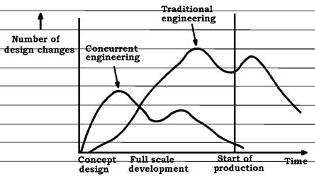
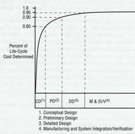
Modern application of the EDP now can incorporate concurrent engineering, which involves teams working simultaneously and interacting to affect the design, instead of sequentially (and independently) like Figure 3. In a corporate setting where concurrent engineering is applied everyone - including engineering, manufacturing, testing, marketing, finance and sales - should be involved, to some level, in all steps of the product life-cycle. For concurrent engineering to work effectively, teams must collaborate, trust and share details across boundaries of design teams and disciplines. “The objective of concurrent engineering is to reduce the product development cycle time through a better integration of activities and processes. Parallelism is the prime concept in reducing design lead time…” [2]. On a SE student project, subsystem teams will need to be involved and cooperating in all steps of the systems engineering design effort. Information is shared among all team members. Shared information is not just drawing and schematics, but also requirements, stakeholder expectations, mission objectives, interfaces between subsystems, concepts, etc. Parallelism for a SE project is also the simultaneous and synchronized design of the subsystems needed to make the system. For example a satellite’s power subsystem is being designed by one team at the same time as the payload subsystem by another team, and it is known that these subsystems will be interacting with each other in some way during operations. To guarantee a successful outcome there must be a synchronization of some activities and a Systems Engineer who is required to provide guidance in the form of interfacing requirements and an architectural design to both teams. Concurrent engineering is a cornerstone of systems engineering. Concurrent engineering in SE can lead to the rapid evolution of concepts and requirements and the avoidance of major mistakes or rework at the project’s end. When concurrent engineering is practiced the design cycle is shortened because fewer design changes occur, they occur more frequently in the earlier formative design stages, and they occur less frequently later in the cycle (Figure 4). Concurrent engineering also reduces cost because design changes later in the process are more expensive than if they occur earlier. Locking in prematurely on an inadequately scrutinized design concept will lead to greater costs down the road from design changes and poor performance from “patch fixes”. Choosing to proceed with development based on a poor design concept can be an expensive mistake, since “at least 80 percent of a vehicle’s life-cycle cost is locked in by the concept that is chosen” (NASA/TP-2001-210992), (Figure 5).
Figure 4. Design Changes as a Function of Time from American and Japanese Automobiles (American Suppliers Institute)
Figure 5. 80% of Life-Cycle Costs is Determined by the Conceptual Design at End of Phase A. Systems
Engineering (SE) and the EDP
When embedded in the Systems Engineering process, EDP is the process used for in-depth, detailed design of parts, components and subsystems. The detailed design of a subsystem itself may be a design task handled by a team whose members are mostly of a single discipline. For example, a team of mostly electrical engineers may design the electrical power system using the EDP. And a team of mostly computer scientists/engineers may similarly design hardware and software for the command and data handling system. Early in the EDP, the systems engineer must make sure the project mission and requirements are well-defined for each subsystem design team and that interfacing subsystems will be designed to integrate into a fully functional product. After the components, subsystems and system are assembled, the systems engineer returns to closely monitor the verification (primarily testing), and validation of the product to insure that it meets performance requirements. In other words, one duty of the systems engineer is to metaphorically provide the "glue" that connects subsystems to create an integrated, fully-functional and tested system, by insuring that concurrent engineering is practiced among subsystem design engineers. But otherwise, designing of the subsystems and components themselves are left to the engineering designers. The Systems Engineering Life CycleThe project life-cycle is broken down into life-cycle phases and detailed in Figure 6. At the end of each phase a decision is made whether to proceed to the next phase or not; this decision is made at, or after a review meeting with relevant stakeholders. Each advancing phase of the life-cycle advances the development and maturation of the system design - from mission objective and initial concepts, to operational system - and beyond to disposal. The Phases of the Life Cycle
Figure 6. NASA Phases of the Systems Engineering Life-Cycle [2] In Figure 6 the life-cycle begins with phases associated with designing (the formulation phases) and includes Pre-Phases A through C. Phase B ends with a preliminary design of a single system, and marks a turning point in the process where significant resources and design effort will be required to complete the design and the remainder of the project phases. The design is completed in Phase C. The latter part of Phase C through Phase F are associated with realizing the physical product - so are called implementation phases - beginning with the procurement and fabrication, assembly of subsystems from components and parts, integration of subsystems to create the system, and continuing on through operations and onto phase-out. A typical student project could start at Pre-Phase A and end in Phase D with testing, although some projects will have a launch and operation at a student competition, for example. At the end of each phase can be a review as named in the Figure 6, where passing the review is a prerequisite to the next phase activities. Later sections describe the specific tasks – the 11 Systems engineering Functions - that a student team must consider in each phase. The Vee Chart Process Model of the Life Cycle
Figure 7. The project life-cycle as a Vee chart (R/A/C are the Requirements, Architectural Design and ConOps steps, SAITL is System Assembly, Integration, Test and Launch), modified from [13]. The Vee Chart (Figure 1 and repeated in Figure 7) is a tool to help students remember and apply the life-cycle process. The phases are on the legs of the Vee Chart, beginning at the top of the left leg. The phases on the left leg (Pre-Phase A through Phase C) are the formulation phases, and are also called the decomposition and definition sequence. Decomposition and definition is logically “tearing down” the system to eventually reveal the complete system architectural design. That is, the system is decomposed and defined from the systems level to the component level as the design process progresses down the left side of the Vee. Advancing upward on the right leg are the implementation phases, also known as the integration and verification sequence contained in Phase D. Proceeding up the right leg is equivalent to “building up” the system from the component level to a completed functioning system, but now with physical components. Notice that some phases have been split to separate tasks within certain phases, e.g. D(1) through D(4) on the right leg of the Vee Chart. Notice also that boxes on the same horizontal level on the left and right side are at the same level in a system hierarchy. For example, phase B and Phase D(2) both operate on the subsystems level. Phase B is concerned with the subsystem level architecture (block diagram), requirements and a subsystem verification plan, whereas Phase D(2) is concerned with building the subsystems and verifying using the Phase B verification plan. Verification plans (discussed below) are test plans written during the formulation phases, and verified (i.e. tested) during the implementation phases. The verification plans are required at the systems level, subsystems level and sometimes for certain components. The Vee chart is divided by a horizontal dashed line that reveals the responsibility boundary between the systems engineering tasks and the tasks typically performed by the design engineering teams applying the design process to create a detailed design of a subsystem. This boundary illustrates that systems engineering is not concerned with detailed design, but are responsible for defining subsystem architectural design, interfaces and requirements. Lastly, it should be mentioned that the systems engineering duties may not all be handled solely by a single person; the systems engineer may assign systems engineering tasks to others. The purpose of a document called the SEMP (Systems Engineering Management Plan, discussed below) is assigning and coordinating Systems Engineering tasks. The 11 SE FunctionsThe 11 Systems Engineering functions are shown in Figure 8 (from [10]), and include the five functions associated with the triangle, as well as six other SE functions. The functions are a set of actions for each phase. The mission objectives initiate the process. The three major functions at the corner of the triangle – Derived Requirements, Architectural Design and Concept of Operations (ConOps) – are the most significant. The triangle is a process flow, it shows the interdependence of the ConOps, requirements and architectural design by the “Validate and Verify” arrows; it also is meant to convey that the ConOps, requirements and architectural design must be consistent with one another and can be iteratively refined. The completed Derived Requirements, Architectural Design and Concept of Operations define a new system for that particular phase of the process. The process of defining a new system must also take into account the “Other SE Functions” (functions 6 through 11).
Figure 8. The 11 Systems Engineering Functions, including the iterated functions shown on a triangle [10] The 11 SE functions are applied in Pre-Phase A through Phase D of the project, one phase at a time, as will be explained later. The completed 11 SE functions of each phase serve as the inputs for the next phase. The entire process, including all the phases, is the Project Life Cycle. Each succeeding phase is additional progress toward a completed system. The process begins with “mission objectives” in Pre-Phase A and ending with an operable system at the end of Phase D. Application of these functions with expert precision and rigor will do nothing for a poor design, breaking the laws of physics, the wrong technology, or flawed assumptions. Keep in mind that even razor sharp tools are only as good as the artesian using them. The double arrows around the triangle mean that the process can proceed clockwise, counterclockwise, or can return back to a previous step if iteration is needed, and can be performed in any order, as well as nearly simultaneously. This is called the “Doctrine of Successive Refinement”, which is a recursive and iterative design loop driven by stakeholder expectations where strawman architectural designs, ConOps (Concept of Operations) and the derived requirements are developed. When there are multiple feasible alternatives they need to be compared and the best selected; a trade study can help in this process. Tools like functional analysis, as was used in the EDP, can be also applied here to stimulate creativity. Successive refinement leads to successively greater resolution further down the hierarchical tree of the system, subsystems, and components. The 11 Systems Engineering Functions in DetailSo what are the tasks that must be considered in each phase? The tasks are the eleven systems engineering functions [10]. Each is explained below. Chapter 3 is a documented example of application of the Systems Engineering process to a Cube Satellite that students can refer to as they apply the 11 Systems Engineering Functions. SE Function 1: Mission Objectives and ConstraintsA mission is an activity to pursue stakeholder(s) goal. Mission objectives are statement(s) that clearly document the goal(s) and constraint(s) of the mission. The mission objective follows from the stakeholders' (i.e. the customers and other interested parties) expectations. Constraints are limitations on the project that the stakeholder may impose. Mission objectives are at the forefront of every stage of the effort, but are not usually captured as “shall” statements like requirements. Mission objectives are normally baselined (requiring formal approval for changes) in Pre-Phase A, but judgment and logic should be used to challenge them when appropriate. Examples of Mission Objectives A
Mission Objective for the Apollo Missions: Transport
a man to the moon and return safely before 1970. Two
Mission Objectives for the Apollo 12 Mission, from
http://www.nasm.si.edu/collections/imagery/apollo/AS12/a12mo.htm: 1) “Perform inspection, survey and sampling in lunar mare area”, 2) “Develop capability to work in the lunar environment.” Mission
Objective for the Apollo 8 Mission, from
http://www.lpi.usra.edu/expmoon/Apollo8/Apollo8.html : “The overall objective of the mission was to demonstrate command
and service module performance in a cislunar (between the Earth and
Moon) and lunar-orbit environment, to evaluate crew performance in a
lunar-orbit mission, to demonstrate communications and tracking at
lunar distances, and to return high-resolution photography of
proposed Apollo landing areas and other locations of scientific
interest.” Primary Mission Objective for the FireSat Satellite [11] (two satellites for detecting and monitoring ground fires): “ To detect, identify and monitor forest fires throughout the
U.S., including Alaska and Hawaii, and in near time”. For
a teleoperated lunar excavator created by a student team: “Create a lunar excavator prototype for studies on the earth that will connect to a standard NASA mobility platform plate". The sponsor also attached the following phrasing which was later translated to system level requirements: "where there is 19" from ground to bottom of excavator-rover interfacing plate, which dumps the soil into an attached bin. The excavator weighs less than 100 kg (not including the bin and mobility platform). Target less than 150 W power and capable of digging 250 kg/hour of regolith, and can be controlled from an out-of-sight ground station." SE Function 2: Derived Requirements DevelopmentDerived Requirements, or simply denoted as
requirements,
are succinct statements that state what must be accomplished,
how well it is to be accomplished, and under any constraints or
limitations. Requirements are applied to hardware,
software, interfacing elements and for testing. Requirements
derive and evolve as the SE process
progresses through the phases; they can be instigate and derived
from stakeholder expectations, mission objectives, a natural
consequence of adding more architectural design detail, trade studies, etc. Requirements
are level dependent; they should be categorized by level, i.e.
mission or system (top level), subsystem, or component (bottom
level) requirements. Requirements can “flow down” from a previous phase or from a higher
hierarchical-level element, e.g. a subsystem requirement may
naturally flow from a system requirement. Requirements will
be the binding contract between the stakeholders, designers and
systems engineering so they must be completely reviewed by all
parties.
There are many kinds of requirements. Requirements often have associated measures of performance (MOPs) or measures of effectives (MOEs). MOEs are related to operational performance and are not a minimum or maximum constraint limitation. For example the amount of scientific data the mission will produce is an MOE that can be used to compare two feasible alternatives, or can be attached to a system-level operational requirement. MOPs are quantitative measures that "characterize physical or functional attributes" and can be attached to requirements; for example the minimum power required, maximum pointing error, thrust required, weight limitations, etc. Within each hierarchical level, requirement types include, with examples: 1. Functional requirements – requirements on what functions the system/subsystem/component must perform. Examples: a. “The
Thrust Vector Controller shall provide vehicle control about the
pitch and yaw axis” [2]. (This
is a requirement for the Attitude Control Subsystem) b. “The
ground station shall provide communication between the excavator and
the human operator” (This is a requirement for the Ground Station
Subsystem) 2. Performance requirements – requirements on how well a system/subsystem/component must perform its function. These are often called specifications and are often associated with a functional requirement. Because they have an associated MOP, the physical element can be verified in Phase D. Examples: a. “The
Thrust Vector Controller shall gimbal the engine a maximum of 9
degrees.” (An
Attitude Control subsystem requirement) b. “The
excavator shall use less than 150 W power.” (A
system level requirement) c. “The
communication subsystem shall be operable within a temperature range
of xx – xx degrees centigrade. (A Communication subsystem
requirement) 3. Interface requirements – requirements on how interacting systems/subsystems/components coordinate activities or mate. Examples: a. “The
excavator must mechanically attach using space-rated bolts to the
chariot interfacing place provided by KSC”. (A system level requirement) b. “The
voltage supplied from Electrical Power System to the Comm and C&DH
systems shall
be 12V +/- 3 V” (A requirement for all three subsystems) 4. Verification
requirements -
requirements that refer to a test, demonstration, analysis or
inspection of the performance or operation of an element, most
likely to be performed in Phase D. Verification
requirements are composed during the formulation phases, and are
documented in the verification
plan. By end of Phase B the verification plan should be
baselined and placed under configuration management. See
systems engineering function 5 for more details. Example: “All
functional and performance requirements of the cubesat shall be met
after thermal bakeout testing performed in a vacuum chamber to a
vacuum level of 5 x
10-4 Torr pressure
per cubesat thermal bakeout test procedure.” 5. Other requirements - such as reliability, regulatory, safety, physical, technical, environmental considerations. Example: “The system will automatically shutdown if the temperature exceeds 200 degrees C.” (A system-level requirement) A good requirement contains one idea, is clearly written (so that it
is not open to interpretation) and is easily verified so that it can be checked whether it
is met or not. Requirements are often expressed as “shall”
statements. A
requirement should also be general enough so as not to severely
restrict design options unnecessarily. Requirements should be documented and organized hierarchically (like Figure 9 or in outline form) to show the parent to child relationship or “traceability”, first for the mission or system (the highest level), then subsystem and finally component and part level (the lowest level); you will notice that the requirements hierarchy should be consistent with the product hierarchy described in the following section on Architecture and Design. Requirements will eventually all be stored electronically, available to all working on the project, and will be presented at the end of each phase at the design reviews. After a successful design review they will be baselined. More examples can be found in the CubeSat chapter 3.
Figure 9. Requirements in a Hierarchical Tree SE Function 3: Architectural Design DevelopmentAn Architectural Design (or just an architecture) is a “description of the elements, their interfaces, their logical and physical layout and the analysis of the design to determine expected performance” [10]. It is not a detailed design. It begins as a product hierarchy (like an "organizational chart" created in PowerPoint) in Pre-Phase A with only one or two hierarchical levels of subsystems, becoming more detailed by adding more levels as a team progresses through the phases. Figures 10 through 13 shows block diagram representations of the STS, with each added product hierarchical level (tiers in the figures) delving deeper into the system's hierarchy. The system is on the top tier, then subsystems, and components on the bottom tier. An architectural design is not just a hierarchy; it can also eventually include a listing of software functions, CAD 3-D renderings, communication flow and wiring diagrams, and subsystem interface diagrams (N-squared diagrams) also. Creating a Pre-Phase A candidate architectural design requires innovative thinking. Candidate architectural designs must have enough detail so that they can be compared and merits assessed (by analytical models, proof-of-concept prototypes, technical studies and other methods that will provide data for a trade study). An architectural design completed in Phase B serves as a starting point for design engineering teams, who will create the detailed design in Phase C (the detailed design will provide dimensioned parts, bill of materials, detailed printed circuit board layouts, pin diagrams, etc.). Example
Figure 10. Product hierarchy through tier 1, Pre-Phase A. Perhaps one of many architectures considered in Pre-Phase A.
Figure 11. Product hierarchy through tier 2, orbiter only, Phase A.
Figure 12. Product hierarchy through tier 3, orbiter avionics system only, also from Phase A.
Figure 13. Another example of a product hierarchy for a system architectural design of a cube satellite at End of Phase B. Each hexagon is a subsystem. Notice the interfaces (lines) between the subsystems. Functional analysis is a useful tool for creating architectural designs. Functions are listed and mapped to elements that are created to perform that function (see the previous mousetrap example). For an excavator, trade studies could be performed to choose a power system (e.g. solar cells, batteries, a combination of solar cells and batteries, unspent rocket fuel, fuel cells, nuclear power, etc.), specific battery type, microcontroller type and features, etc. Most trade studies are performed during Phase A. It can either be a formal process (with a ranking system based on selection criteria) or informal using logical arguments. Examples of trade studies are included in Chapters 3 and 4. SE Function 4: Concept of OperationConcept of Operations (“ConOps”) is a description of how the system will operate during the mission to meet stakeholder expectations [4]. It describes the system characteristics from an operational perspective and helps facilitate the understanding of the system goals. It is a time ordered list of a sequence of steps, or graphically represented like Figure 14 below. See Chapter 3 for another example. Example:
Figure 14. Example of a Concept of Operation, in graphical form [2] SE Function 5: Validate and VerifyValidate and Verify (V&V) is an SE function that is ongoing during requirements, architectural design and ConOps creation in the formulation phases, and establishes test procedures for Phase D. There are 2 aspects to V&V: 1) during the formulation phases making sure there are no inconsistencies in the requirements, ConOps and architectural design, and 2) planning for V&V physical testing by creating a verification plan during Phase B and executing the testing in accordance with that plan during Phase D. The verification plan includes verifying subsystem requirements are met by physical testing of the subsystems (Subsystems Requirements Verification), verifying system-level requirements are met by physical testing of the system (System Verification) and validating the system (System Validation) as explained below. Subsystems Requirements Verification is proving that each requirement on each subsystem is satisfied (and sometimes components may be subject to their own requirements and need to be tested). Requirements verification in the formulation phases can be performed by proof-of-concept prototypes, computer simulation to predict performance, engineering analysis, physical testing, an inspection or a logical argument [12]. In Phase D, subsystems' requirement verification is primarily accomplished by physical testing of the subsystems separately. For some requirements to be verified it will be necessary to create associated Verification Requirement(s); these form the basis of physical testing in Phase D and an example is shown below. Example 1 - Requirement on the Comm
Subsystem with Verification Requirement Requirement: The probability of a bad
telecommunication bit from a ground station to the excavator
shall be less than .0001. Verification Requirement: Laboratory testing of the telecommunication system will be performed during a 5 minute communications tests and the test will be considered successful if the probability of a bad bit is less than .0001 Example 2 - System-level Requirement on the Natural Frequency of the Excavator with Verification Requirement Requirement: The first natural frequency in
bending of the extended excavator shall be greater than 20 Hz Verification Requirement: The first natural
frequency in bending shall be tested on a vertical shaker, with
excavator connection points attached to the shaker and the excavator
fully extended. A successful test will have a first natural
frequency in bending of less than 20 Hz.
System Verification is assuring that the entire system is built right. (Again, by our convention, the "system" is the entire final integrated product). System verification determines whether or not the product meets the system level functional and performance requirements. Proof of compliance can involve 1) testing, 2) inspection, 3) demonstration and/or 4) analysis, of which testing is the most important method of proof. It is "kicking the tires" and putting the system through its paces, looking for defects in the design and implementation. Testing of the system can also involve environmental testing - including vibration and shock, thermal and vacuum testing, and radiation and electromagnetic testing. System Validation is assuring that the right system is built. System validation testing occurs at the end of Phase D and is meant to demonstrate whether or not the mission objective(s) are met. To do so it should obviously function as intended, be safe, reliable, and affordable (in essence validation is a a sanity check). In the formulation phases system validation is achieved by adhering to and being guided by the mission objective. During implementation, system validation is achievable by a test where the entire system is exercised through a demonstration of how it would operate in a mission (e.g. a simulated ConOps), perhaps in an environmental test chamber or at a location that recreates some or all of the environmental conditions expected during the mission. A Verification Plan to perform the testing in Phase D for Subsystems' Requirements Verification, System Verification and System Validation is prepared in Phase B, and at that time arrangements made for special equipment for the testing to take place in Phase D. SE Function 6: Interfaces and ICD (Interface Control Document).Interfaces are boundaries between elements. The interfaces evolve as the architecture/design proceeds from higher level to lower level, and interface requirements are created. The ICD is a document prepared by Systems Engineering that specifies the mechanical, thermal, electrical, power, command, data, and other interfaces. The document is first prepared in Phase B, and updated for each review. Example from the CubeSat Chapter - C&DH System Interface connections: Confirm antenna release, Antenna release, Power in, Ground, Data
in from comm, Data out to Comm, PTT control, VX-2R power control,
Decoder/Encoder, Antenna switching control, Temperature sensors
(Solar cells, 2 Batteries, 2 Microcontrollers 1 and 2, VX-2R,
payload), Voltage sensors (Solar cells, 2 Batteries, 2
Microcontrollers, Payload), Payload data in. SE Function 7: Mission EnvironmentAll contributing members to design and testing must be made aware of the mission environment. This information must be documented and available. Environmental concerns and exposures include vibration, shock, static loads, acoustics, thermal, radiation, single event effects (SEE) and internal charging, orbital debris, magnetic, and radio frequency (RF) exposure. Chapter 5 presents a description of the lunar environmental conditions in which an excavator will operate. SE Function 8: Technical Resource Budget TrackingTechnical resource budget tracking identifies and tracks resource budgets, which can include mass, volume, power, battery, fuel, memory, process usage, data rat, telemetry, commands, data storage, RF links, contamination, alignment, total dose radiation, SEE, surface and internal charging, meteoroid hits, ACS pointing and disturbance and RF exposure. Below is an example of a tabulated budget, in this case a mass budget.
Figure 15. Mass budget example, this time for the Command and Data Handling System (the tabulated mass here should be less than an allotted amount, as would be defined in a requirement). SE Function 9: Risk ManagementRisk relates to undesired events and consequences that can adversely affect the project or mission. Risk is particularly important in a space mission, where missions are expensive and repairs may be impossible. Risk management identifies the risks to safety, performance and the program (cost overruns and schedule delays), and establishes approaches to mitigate (i.e. make less severe) the risk. Performance and safety risk may be a design consideration, calling for a design change or improvement. There are many types of risk including failure during the mission (operational risk), failure to meet deadlines (schedule risk), failure to stay below a budgeted cost (cost risk) and technical performance risk (failure to meet requirements, such as mass budget). The steps of risk management are 1) Seek and identify the risks, 2) Determine their severity and effect of the risk, and 3) Develop methods to mitigate the risk. The steps can be performed in a table as a method called Failure Modes Analysis. First a table like Figure 16 is created that codes the severity of a risk from 1 (non-critical failure) to 4 (entire mission failure). In Figure 17 the risk, code, effect and mitigation strategy are presented in an example. Mitigation can be achieved by providing redundant components, fault tolerant components, and error detection methods.
Figure 16. Four failure classifications and their failure code
Figure 17. Example EPS Failure modes, codes, effects and mitigation SE Function 10: Configuration Management and DocumentationConfiguration management is a system for documentation control, access, approval and dissemination. After every review and as the life cycle progresses, certain documents are baselined (A baseline is a set of documents such as CAD drawings, schematics, architectural designs, requirements, trade studies, risk analyses, SEMP, ConOps, bill of materials, etc. that will have changes controlled through a formal approval process). The Systems Engineer controls access to these documents, and must approve and track any changes. Baseline documents can be stored in a computer library (e.g. a drive dedicated to the project) that other team members can have read access. Other documents worth storing can include manufacturer’s data sheets of components and instruction manuals, review reports and presentations. SE Function 11: System Milestone Reviews and ReportsReviews are presentations with a report to the stakeholders, and are denoted by a milestone on a project schedule like the triangle marks in Figure 19. Milestones highlight a tentative date of any important upcoming project event like reviews, project start date, a scheduled date for testing, etc. Milestone can also mark an achievement, such as successful completion of a phase to the satisfaction of the stakeholders. Milestones can also mark a control gate or key decision point (KDP), in our case the decision date by the stakeholders whether to proceed or not to proceed to the next phase activities. A milestone denoting a review date could be followed by a KDP a few days later, or one milestone could denote both events. Reviews products are the evidence that the project has completed a particular phase of a life cycle. The review products include the documents (presentation, reports and any hardware or software demonstration models) and these are transferred to the configuration management system and baselined. The common reviews at the end of each phase are: Pre-Phase A - Mission Concept Review (MCR) Phase A - Mission Definition Review (MDR) or System Definition Review (SDR) Phase B - Preliminary Design Review (PDR) Phase C - Design Review (DR) or Critical Design Review (CDR) Phase D – Readiness Review (RR) or Operational Readiness Review (ORR) Reviews can be combined, e.g. the MCR with the SDR, and/or the PDR with
the CDR.
Each review should include a Power Point presentation, plus a formal,
fully-detailed
report. The format of the report should include three main sections
– Systems Engineering, Project Management and Subsystems Design
Engineering. Within the Systems Engineering section the report
should address each of the 11 SE functions, but focus on the first
five. The Project Management section includes the management functions
(scheduling of reviews, task management and costs and budget) listed
in "Successfully Managing a
Systems Engineering Project
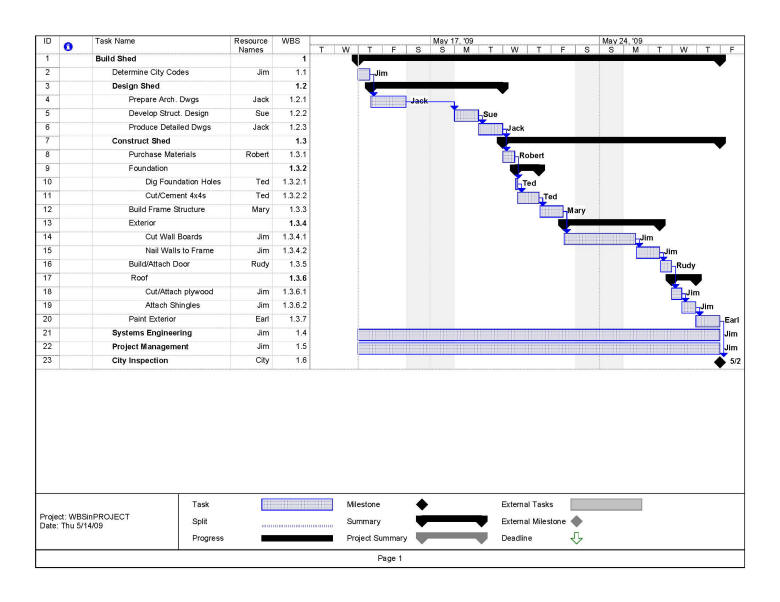
Figure 18. Review Report Format The report may include Gantt Charts, which are horizontal bar chart with each bar representing a task, and the extent and placement of the bar showing the task duration and finish date. A Gantt Chart can be used to allot time to tasks, schedule reviews, and date milestones. Tasks are the project activities. Tasks have start and end dates. Often a task is written as a phrase starting with a verb (e.g. “creating product”). Each task has a start time and end time. The chart often needs to be updated since end dates are usually estimates and tend to slide. A Gantt Chart should be created to schedule important events in the project. Gantt Charts like Figures 20 and 21 can be created in MS Excel or MS Project. Meetings, reviews, KDPs and other milestones can appear as triangles, diamonds or other symbol, rather than a line for how long the item takes. A Gantt Chart is a tool of project management, and should be presented in the project management section of the report.
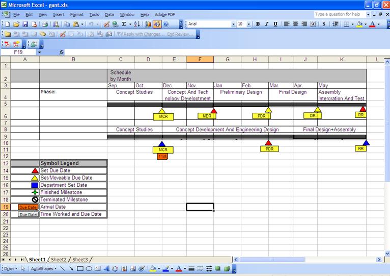
Figure 19. Milestone chart using MS Excel, showing two projects. The project on the top level shows the five reviews, and the other project shows only three reviews.
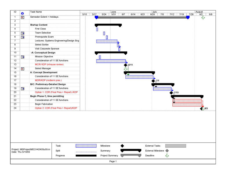
Figure 20. Semester Gantt Chart schedule of reviews and milestones, created in MS-Project
Figure 21. Example Gantt Chart schedule from NASA Systems Engineering Handbook [2] The Phases Activities in DetailPre-Phase A - Concept StudiesPurpose: To produce a broad spectrum of ideas and alternatives concepts. Activities: The Systems Engineer leads a team of engineers or subsystem team leads who innovate, in a loosely-structured manner. Small studies might be performed, as assigned by the Systems Engineer. 1. Begin
the SE process by identifying, understanding and documenting mission
objective(s). Concentrate
on understanding the true or
fundamental desired outcome and restrictions. Even consider that the
customer may have provided incomplete, unintended, or erroneous
direction toward what they intend to achieve and go back to ask for
clarification or feedback.
2. The 11 SE functions are applied (perhaps loosely), creating a broad spectrum of alternative concepts – including associated requirements (draft top-level system requirements), architectures and ConOps. The alternative concepts are visualized at the highest levels (e.g. the shuttle transport system consists of the orbiter, booster and external tank as in Figure 10), although more subsystem details may need to be "on the table". Systems Engineer’s Report: The Systems Engineer prepares a report that addresses each of the 11 SE functions of Figure 8. Review: Mission Concept Review (MCR) presentation + report. Follow format of Figure 18 loosely – it is not necessary for subsystem leads to present or create a report. Focus on presenting the mission objective and the feasible alternative architectures, with requirements and ConOps. It is possible for a student team to skip the Pre-Phase A presentation/report, and incorporate these findings in Phase A presentation/report, and store at a configuration management site. Phase A - Concept and Technology DevelopmentPurpose: To determine the feasibility and desirability of a suggested new major system. Activities: The System Engineer leads all Phase A activities with support from subsystems lead personnel 1. From several alternative concepts, down select to a single conceptual system. (To choose among design alternatives here (and also anywhere in the life cycle) it may be necessary to perform trade studies). 2. For the single conceptual system, apply the 11 SE functions. In particular: a. (Functions 2, 3 and 4): Produce system (top-level) requirements and a system architectural design and ConOps. b. (Functions 2, 3, 9 and 10): Propose an architecture thru the subsystems, and subsystem requirements, and anticipated performance of each, then identify major components of the subsystems. When doing this, perform trade studies as needed among alternatives, identify risks and perform necessary analyses. Baseline system-level architecture and system-level requirements. (A baseline is a set of documents (drawings, schematics, requirements) that will have changes controlled through a formal approval process and are an archived configuration) c. (Function 8): Subsystem budgets (e.g. power, cost, mass, etc.) are allocated to the subsystems. 3. Program manager develops first estimates of costs and schedules. Systems Engineer’s Report: Systems Engineering prepares a report that addresses each of the 11 SE functions of Figure 8, including subsystem requirements with help from the subsystem team leads. Store at a configuration management site. Subsystem Teams’ Reports: Subsystem teams work and report on early progress on the subsystem design effort (including subsystem trade studies, CAD, schematics, rough bill of materials, risks, engineering analysis, etc.). Store at a configuration management site. Review: System Definition Review (SDR) presentation + report. Follow format of Figure 18, updated from the MCR. Phase B - Preliminary Design and Technology CompletionPurpose: To define the project in enough detail at all levels (system, subsystem and components) to establish a Preliminary Design that has no unresolved design or technology issues. Per [2], a Preliminary Design “meets all the system requirements with acceptable risk and within cost and schedule constraints and establishes the basis for proceeding with detailed design. It will show that the correct design option has been selected, interfaces have been identified, and verification methods have been established.” Activities: (The
System’s Engineer leads all Phase B SE activities with support from
subsystems lead personnel, who will likely have his/her subsystems
team support the SE effort as described below. Systems
Engineering produces the architectural design, "design to"
requirements, interfaces, and verification plan. The Systems Engineer is not involved in
the detailed design engineering of subsystem except to orchestrate
issues arising between subsystems, at interfaces, or impacts to
mission requirements.) 1. For the single conceptual system, apply the 11 SE functions to advance the project. The focus is on subsystems (Requirements, ConOps and architectural design and their interfaces). Special considerations when applying the 11 SE functions are: a. (Function 2, 3, 6): The detailed design effort for each subsystem is primarily performed by the subsystem design engineering teams later in Phase C. However in a student project the subsystem design engineering teams are the ones exploring design alternatives at the subsystems level, addressing unresolved technology issues, defining some subsystem details (e.g. interfaces, components). In essence, they have begun the EDP on their subsystem and progressed through Phase 3 (Concept Generation and Evaluation Phase). This early design effort will feed information to systems engineering who will create 1) the "design to" requirements for the subsystem design teams to meet with their detailed designs, 2) Phase B architecture with interfaces, and 3) verification plan. b. (Functions 3, 9): Subsystem design concepts are developed and all high-risk areas resolved (i.e. complete the technology); resolve all design issues so detailed design can begin in Phase C. c. (Functions 3, 9): If necessary model the system using techniques such as analytical modeling, state machines, block diagrams, computer simulations, CAD, mock-ups, proof-of-concept prototypes and mental models to compare alternative designs and to resolve high risk areas. Build demonstrational or proof-of-concept prototype(s) if needed for technology completion, so that unproven technology can be proven before going onto Phase C and the detailed design tasks. d. (Function 8): Systems Engineering allocates the resources to hardware elements and software (e.g. tabulates and budget mass, power, etc.) e. (Functions 5, 6): Systems Engineering develops verification test plans from verification and validation, defines interfaces with an ICD, identify risks and develop mitigation strategies. f. (Functions 2, 3, 4, 10): The Systems Engineer develops baseline system and subsystem requirements, system architecture (like Figure 13) with subsystems, and ConOps. 2. Program manager improves estimates of costs and schedules. Systems Engineer’s Report: Systems Engineering prepares a report that updates each of the 11 SE functions from Phase A, including subsystem requirements. Report on all system and subsystem level trades and update from Phase A. Subsystem Teams’ Reports: Each subsystem team report details the "preliminary design" of their subsystem (e.g. schematics, conceptual undimensioned 3-D CAD drawings, estimated bill of materials, engineering analyses, resource need estimates, proof-of-concept prototype testing, requirements, risk analysis if needed) and shows that there are no unresolved technology or design issues remaining. Review: Preliminary
Design Review (PDR) presentation + report. Follow
format of Figure 18, updated from the SDR.
Phase C - Final Design and FabricationPurpose: To complete a detailed final design of hardware and software (i.e. drawings and specifications to fabricate or procure the hardware and code software, and to assemble systems and subsystems). Activities: (The
System’s Engineer leads all Phase C SE activities with support from
subsystems lead personnel. The
Systems Engineer is not involved in the detailed design engineering
of subsystem except to orchestrate issues arising between
subsystems, at interfaces, or impacts to mission requirements.) 1. Update the 11 SE functions. In particular: a. (Functions 3, 10): Subsystem Teams produce final designs with bill of materials, detailed drawings, schematics and specifications for production in Phase D. Plan fabrication and procurement of hardware and code software. Fabricate and procure hardware after successful review. Subsystem engineering teams are heavily involved creating a detailed design and engineering specifications for their subsystems and components. The design documentation becomes a “build-to” baseline. Systems Engineer’s Report: System’s Engineer prepares a report that updates each of the 11 SE functions of Figure 8. Subsystem Teams’ Reports: Subsystem teams prepare a design report/presentation of a final design to 1) demonstrate completion, 2) baseline the design, 3) plan fabrication and procurement of hardware and code software. Review: Critical Design Review (CDR). Fabricate and procure hardware after successful CDR. Phase D - System Assembly, Integration, Test and Launch (SAITL)Purpose: To
assemble parts and components to create the subsystems, integrate
subsystems to make the entire system, to test the subsystems and
system to be able to meet requirements, and finally to launch the
system.
Activities: The Systems Engineer is very involved in evaluating and qualifying the system based on verification and validation test procedures for components, subsystems and system. Perform environmental testing. Resolve any discrepancy of performance with requirements. Prepare an operator’s manual and, if needed, include maintenance, storage and shipping procedures. Demonstrate the system at a Readiness Review (RR) or Operational Readiness Review. Systems Engineer’s Report: Report on the test results, including ability of the system to meet requirements, mission and functional performance. If there are any changes in the 11 SE functions and the baseline design, remember to update the documentation to track the changes. Phase E/F - Operations, Sustainment, and CloseoutOperate the system (Phase E) and dispose of properly (Phase F). For more details on operating a system, refer to [2]. Successfully Managing a Systems Engineering ProjectManagement Structure and DutiesA suggested project management structure is shown below. On a small student project it may be permissible to have the Systems Engineer and the Project Manager be one in the same person. The Program Manager could be a professor, graduate student, with possible assistance from a NASA engineer. The NASA engineer normally takes on the role of the customer or primary stakeholder. Subsystem teams on the lowest level of Figure 22 are managed by student subsystem team leads, e.g. COMM would be managed by an electrical engineering student since the team is most likely made up of electrical engineers, Structures by a mechanical or aerospace engineering student, Payload might be managed by a physics student if it is a scientific mission, etc. The subsystem teams are responsible for the design and construction of their own subsystem, components and parts (if not COTS). Subsystem team leads may also be part of the Systems Engineering team, hence they work closely with the Systems Engineer on the SE functions.
Figure 22. Example project management structure for a student team. Subsystem team leads on the bottom tier manage their subsystem teams, and could also be a part of the systems engineering team. Systems Engineer Duties and TraitsAccording to [3], the function of systems engineering is to “guide the engineering of complex systems” and to form bridges across traditional engineering disciplines who are designing the individual subsystems that must interact with each other. A good systems engineer is creative and likes to solve practical problems; is open minded to new ideas but is skeptical if they are unproven; enjoys new challenges outside his/her “comfort zone”; is knowledgeable in several engineering areas and remembers and absorbs new information quickly [3]. Very important traits are good interpersonal, writing, and verbal communication skills. He/she must be a good “general”. It is also important that the systems engineer have personal integrity and be a motivator [15]. It is not intended that all the Systems Engineering tasks are performed by the Systems Engineer, but are assigned by the Systems Engineer to members of a systems engineering team in the Systems Engineering Management Plan or SEMP (described later). In summary, the systems engineer is responsible for guiding the engineering of the project. This includes [2]: · Leading the development of the systems architecture · Defining, verifying and validating system requirements, and their flow down the system hierarchy · Evaluating design tradeoffs from trade studies · Responsibility for guiding the integration and test phases of the project · Balancing technical risk between systems · Defining and assessing interfaces · Providing oversight of verification and validation activities · Responsibility for coordinating and managing o trade studies o critical resources o failure mode and risk analysis · The systems engineer will usually have the prime responsibility in developing many of the project documents, including o The Systems Engineering Management Plan (SEMP) o Requirements documents o Verification and validation documents o Other technical documentation. Subsystem Team Lead DutiesEach subsystem lead is responsible for the development and testing of their individual subsystem, and must remain aware of how changes in their subsystem affect other subsystems and the system as a whole. Subsystem leads may be assigned Systems engineering functions concerned with their system. Project Manager DutiesSystems Engineering is considered a part of project management. The jobs of the Project Manager include supervision of the Systems Engineer and making the important decisions, as recommended and in consultation with the Systems Engineer and subsystem team leads. The project manager has several other duties, including 1) creating a time schedule, 2) managing tasks and 3) monitoring expenses and staying within budget. All these tasks can be performed in MS Excel or MS Project. Time Scheduling Scheduling of reviews, milestones and key decision points can be performed using a Gantt Chart as described in the section covering SE Function 11.
Managing Tasks using a Work Breakdown Structure A tool for scheduling and tracking tasks is a Work Breakdown Structure (WBS). A WBS is a hierarchical breakdown of the project work, and that can also include the deliverable items and services. It divides the project into manageable tasks, and next, responsibility for accomplishing that task can be assigned. It can be represented in a hierarchical tree form; on the bottom level of each branch of the WBS is the task, and optionally the person assigned that task. A WBS can be used during the formulation phases of student projects, it is very useful during implementation. Examples of WBS in a hierarchical tree form and Product Breakdown Structures (PBS) are shown in Chapter 4. A WBS can also be represented in a Gantt Chart and outline form as shown in Figure 23, which was created in MS-Project [18]. It presents a list of the tasks to "Build a Shed" in a numbered outline hierarchy in the column labeled "WBS". The responsible person for each task is listed in the column "Resource Names". The tasks are on the bottom-most outline level of the entries in the "WBS" column, with names of the individuals who are responsible for that task. Note that the WBS includes tasks that are not products, such as the "Systems Engineering" task, "Project Management" and "City Inspection". MS-Project is very powerful and possesses other features and capabilities for project management besides what are demonstrated here. Figure 23 could also have been created in MS-Excel.
Figure 23. A Work Breakdown Structure created on MS-Project.
Systems Engineering Management Plan (SEMP)Below is presented an outline of a SEMP, which should be prepared by the Systems Engineer. “An important part of Systems Engineering is planning the systems engineering activities, what is done, who does them, how it is to be done, and when the activities are expected to be complete. The purpose of the Systems Engineering Management Plan is to document the results of the planning process.”[10] Outline of Systems Engineering Management Plan (SEMP) for a Student Project [10]A SEMP is a planning document that should be baselined by the Systems Engineer at the end of Phase A, and formally updated as needed thereafter. It primarily schedules activities and reviews, and assigns SE functions. The level of detail necessary here depends on the size of the team, scope of the project, etc. 1. Mission objective, project schedule with life cycle, gates and reviews. Work this in association with the project manager. 2. Communication: Describe methods utilized for communicating systems engineering activities, progress, status and results. Include any periodic meeting or working groups. 3. Systems Engineering Functions The Systems Engineer will assign who is
responsible for and documenting of Mission Objectives(s), ConOps, Architecture/Design,
the , Verification and Validation, the
requirements and hierarchy, configuration control (when documents
are placed under formal control, archived and method of distributed)
and management, verification activities and tracking, interfaces and
ICDs, mission specific environment levels and limits, resource
budgets, risk management and acceptable risk.
4. Systems engineering Management The Systems Engineer will assign who is responsible for 1) Systems Engineering Organization Chart and Job Responsibilities, 2) trade studies, topics, who does them and when they are due. Fundamental Principles of Successful Systems EngineeringSystems engineering is most probably best learned “by doing”. What is presented in this document is a roadmap based on the Vee Chart and the 11 Systems Engineering Functions to help the student through the process. At this point there are several points and fundamental guiding principles that will aid the process. · The rigorous processes in [2], [10] is meant for large scale projects and is not appropriate for a student team with limited time. There is a lot of discussion in the literature that SE has become so rigorous that it can be intellectually confining and in so doing impedes creativity [16] as well as becomes the object of the entire endeavor at the detriment of successfully accomplishing the mission goals. The presentation has sought to simplify the process and create a SE roadmap tailored for student teams. Nevertheless, the roadmap can be relaxed and adjusted to better suit your project, course objectives, team size, etc. · Always keep the mission needs at the forefront of the design process, at every phase. · The systems engineer is the guide. It cannot be overemphasized how many projects fail because of poor execution of the in the early phases. Anecdotally, the most common student projects mistakes are: o “Missing the Target”, i.e. designing something that does not meet the customer needs. Often this goes all the way back to Pre-Phase A, where the mission objectives and needs are not entirely understood or probed. This is not the fault of the sponsor, but the fault of the design team, and can result from a lack of communication. Systems Engineering, properly applied, should catch this problem. o “Jumping the Gun”, that is going onto the next phase when unresolved issues remain. For example, new technology sometimes requires that it be prototyped in order to evaluate whether it is going to work at all. At this point either 1) do not proceed to the next phase until the issue is resolved by considering new technologies and evaluating risk of each, or 2) consider revisitng/renegotiation the mission objectives. o Poor documentation can lead to poor corporate memory once an incomplete project is passed to a new student team. Proper application of systems engineering “Configuration Management” should include a method to organize and archive all documents associated with the 11 systems engineering functions. o Systems Engineering is particularly applicable to large scale systems that are made up of multidisciplinary teams. CD&H is best handled by Computer Engineers, EPS is an Electrical Engineering problem and Mechanical or Aerospace Engineers the Thermal and Structures and Mechanisms. If a student team is made up only of one particular discipline, then the mission objective needs to be appropriate for that discipline. For example, a team of computer engineers may apply SE to produce only the CD&H subsystem. AppendixDick Cook’s Systems EngineeringAs mentioned previously, too much attention to the SE process
detail can stifle creativity. The
following section is a “short and sweet” version of system’s
engineering prepared by Dick Cook. Dick
retired as the President of the Electronics Systems Company - Martin
Marietta (now Lockheed Martin) and was the engineering manager for the
design of the Viking-1 Lander. In 1976 the Viking-I performed the
first successful landing on Mars by a NASA spacecraft, which was
designed using Systems Engineering. Systems Engineering - Life cycle
main milestones and associated SE activities 1. Mission
architecture - Define mission elements and interfaces – this is typically simple for cubesats, i.e., spacecraft, ground station, launch vehicle and potentially science. Systems engineering leads this activity with strong support from subsystem lead personnel - Spacecraft envelope – this is typically dictated by the launch vehicle - Weight (mass) - this is typically dictated by the launch vehicle - Environmental requirements - Vibration and acoustics are dictated by the launch vehicle - Temperature and vacuum – determined by the planned mission and the orbital parameters/spacecraft orientation - Determination of orbital parameters based on science requirements and engineering needs (i.e., solar panel orientation, thermal parameters, CG) - Development of the sequence of events of the initial orbital operations to configure the spacecraft for operations - Develop a typical operations orbit - Establish preliminary budgets for subsystems (power, data rates, RF links, mass properties, etc.) 3. Systems
requirements Systems engineering leads this activity with strong support from subsystem lead personnel. This is the phase where you drive down the mission requirements to detailed system requirements. All of the items above are refined to the detailed specification level such as structural dimensions with plus and minus values. Power levels in terms of voltage (i.e., 28vdc +0.5-0.5). System drivers are identified and trade studies are done to determine the optimum solution. Trade studies are performed considering key parameters, i.e., power consumption, weight, volume, space legacy, costs, etc. Risks are identified and the necessary analysis and tests are performed. System requirements, specifications and schematics are released in a formal document and baselined then put under configuration control. Subsystem budgets (power, uplink/downlink, etc.) are allocated and controlled. 4. Preliminary design Systems engineering is still heavily involved but this is the phase where the subsystems participation and manpower loading increases dramatically. This is the period where the subsystem design concepts are developed and all high-risk areas should be resolved. Systems engineering performs the following: - Continue internal/external interface control - Continue to control system budgets and subsystem budgets - Assure that subsystem design concepts are within and compatible with system requirements - Complete all system level trades and update - Assure that subsystem trades are done - Approve the subsystem design concepts, trade studies and risk identification/mitigation Conduct PDR review The conclusion of this phase is the authority to proceed with detail design 5. Critical design Basically, systems engineering continues the above. The result of this phase is the authority to release detailed engineering and begin to fabricate hardware and code software. Systems responsibility throughout the program is to always make sure that: - The design, build and testing is in compliance with the mission and system requirements - Assure that detailed design specifications with tolerances are developed and compatible with system specifications - Configuration control is maintained - Budgets are maintained and adhered to - Environmental levels are maintained and updated -
- Continue internal/external interface control
Further Thoughts on Systems EngineeringFurther insight can be gained from a speech by NASA Administrator Michael Griffin [9] where he provided an overview of systems engineering at NASA. Note his emphasis on the point that precision in doing the process you are learning (requirements, interface, etc.) has little chance of obtaining a great outcome from a flawed concept. This subtlety is all important, not well taught in schools, and often neglected in practice to the costly demise of many. “Systems
Engineering is the art and science of developing an operable system
capable of meeting requirements within imposed constraints. The
definition is somewhat independent of scale, and so these words are
useful only if one understands that it is the big-picture view which
is taken here. We
are talking here about developing an airplane, a spacecraft, a power
plant, a computer network. We are not talking about
designing a beam to carry a particular load across a known
span…….Systems engineering is a holistic, integrative discipline,
wherein the contributions of structural engineers, electrical
engineers, mechanism designers, power engineers, and many, many more
disciplines are weighted and considered and balanced, one against
another, to produce a coherent whole that is not dominated by the
view from the perspective of a single discipline. Systems
engineering is about tradeoffs and compromises, about generalists
rather than specialists……Systems engineering is not about the
details of requirements and interfaces between and among subsystems.
Such details are important, of course, in the same way that accurate
accounting is important to the Chief Financial Officer of an
organization. But accurate accounting will not distinguish between a
good financial plan and a bad one, nor help to make a bad one
better. Accurate control of interfaces and requirements is necessary
to good systems engineering, but no amount of care in such matters
can make a poor design concept better. Systems engineering is about
getting the right design……I like to think of systems engineering as
being fundamentally concerned with minimizing, in a complex
artifact, unintended interactions between elements desired to be
separate….Systems engineering seeks to assure that elements of a
complex artifact are coupled only as intended…..Educators …..are far
less certain how to teach "generalship" than we are of how to teach
the laws of thermodynamics. And yet it is clear that an
understanding of the broad issues, the big picture, is so much more
influential in determining the ultimate success or failure of an
enterprise than is the mastery of any given technical detail. The
understanding of the organizational and technical interactions in
our systems, emphatically including the human beings who are a part
of them, is the present-day frontier of both engineering education
and practice.”
|