ESMD Course Material : Fundamentals of Lunar and
Systems Engineering for Senior Project Teams, with Application to a
Lunar Excavator
Contact: David Beale, dbeale@eng.auburn.edu
Contact: David Beale, dbeale@eng.auburn.edu
|
|
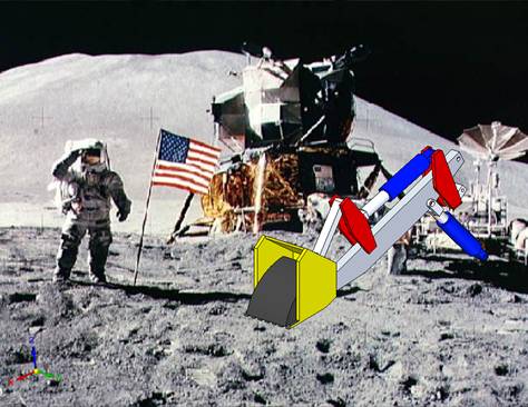
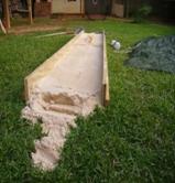
Figure 1 A lunar excavator's mission is to dig lunar soil Chapter X: A Roadmap to Design an Excavator Based on Systems EngineeringThe objective of this chapter is to present condensed and hyperlinked course material that chronologically steps through the systems engineering design process to design an excavator. Following a link will lead to a more detailed explanation and/or additional materials. Contents
So Now What is Systems Engineering (SE)?Systems Engineering (SE) is the engineering process to create a system. It is a structured process based on concurrent engineering and that incorporates the Engineering Design Process. One definition of SE is as follows (NASA Systems Engineering Handbook SP-601S): "Systems Engineering (SE) is a disciplined approach for
the definition, implementation, integration and operations
of a system (product or service) with the emphasis on the
satisfaction of stakeholder functional, physical and
operational performance requirements in the intended use
environments over its planned life cycle within cost and
schedule constraints. Systems Engineering includes the
engineering activities and technical management activities
related to the above definition considering the interface
relationships across all elements of the system, other
systems or as a part of a larger system." The Vee Chart (Figure 9) was created to guide and simplify the application of the SE process through a series of Phases. Within each phase of the Vee chart, you will sequentially consider application of the 11 Systems Engineering Functions (Figure 10). The
Mission Objective
NASA is represented by Robert Mueller as the customer or stakeholder in the project, whose expectations will lead to statement of a mission objective. The team should make sure that the mission objective is clearly stated, it could also include functional, physical and operational performance requirements for the environment and life (in the strictest sense, requirements are not usually a part of the mission objective as presented in Chapter 2, but we bend the rules a bit here). Create a lunar excavator prototype for
studies on the earth that will interface to a NASA mobility
platform (19" from ground to bottom of plate), dumps the
soil into an attached bin, weighing less than 100 kg, not
including the bin and mobility platform. Target less than
150 W power and capable of digging 250 kg/hour of regolith. Create a lunar excavator prototype for studies on the
earth that will interface to a NASA mobility
platform (19" from ground to bottom of plate), dumps the
soil into an attached bin, weighing less than 100 kg, not
including the bin and mobility platform. Target less than
150 W power and capable of digging 250 kg/hour of regolith,
and functions autonomously. The Wireless Excavator Prototype: Create a lunar excavator prototype for
studies on the earth that will interface to a NASA mobility
platform (19" from ground to bottom of plate), dumps the
soil into an attached bin, weighing less than 100 kg, not
including the bin and mobility platform. Target less than
150 W power and capable of digging 250 kg/hour of regolith,
and can be controlled from an out-of-sight ground station. On the moon the excavator will be digging lunar soil called "regolith". The regolith will be needed for a lunar base - for making oxygen, for base construction, etc. The "mobility platform" is a wheeled or tracked vehicle with a motor that will move and locate the excavator. The completed student excavator is attached to a NASA mobility platform via an interfacing plate (see Appendix). You can see a prototype mobility platform at http://www.nasa.gov/mission_pages/constellation/main/lunar_truck.html . Other mission objectives may require you to build your own vehicle to drive the excavator. Create a lunar excavator that dumps the
soil into an attached bin, weighs less than 100 kg, uses
less than 150 W power, is capable of digging 250 kg/hr of
regolith, fits within a cargo space of 1 m3, with
operational lifetime of 5 years, and can be controlled from
a ground station, run either autonomously or from ground
station commands. Be prepared to perform test your prototype. If necessary you can create your own soil bin using sand or other commercially-available material available at a garden center, or consider going to a beach if one is nearby. Dry concrete mix is more representative of the soil properties of regolith than sand and may be the most representative choice of any easily acquired material. In the future expect that locations, such as NASA centers, will have bins loaded with regolith simulant such as JSC-1a for testing.
Background Information and Science
Before going onto the next phase of the design you will need to learn about the moon. Students and practicing engineers will find a hostile environment that requires careful material selection, analysis and design so that equipment will be able to operate successfully. Background Information from Chapter 1
Chapter1.htm#Introduction
· The moon is quite different than the earth as a future sight for habitation. Check out the comparison of the earth and moon. · What is an excavator? An excavator for the earth will look much different than for the moon. As you learn more about the needs of a lunar excavator and the lunar environment, you may not feel these excavator designs are the best choice for lunar regolith excavation. · The history of the lunar missions can be seen at http://www.lpi.usra.edu/lunar/missions/. This is a really neat site. Click on any of the vehicles (orbiters or landers) to learn more about that mission. Look at the LCROSS and LRO missions scheduled for late in 2008, which are intended to look for water in the lunar craters. When NASA next sends humans to the moon, it will be flying the Ares launch vehicle (the rocket) attached to the Crew Exploration Vehicle (CEV) named Orion. · The lunar rover or "moon buggy" operated on the surface of the moon which astronauts drove almost 7 km from the lander. A lot can be learned from successful space systems of the past and applied to future designs. Chapter 6 goes into the details of the design of the lunar rover . · Much of the future lunar base will be constructed by robots like "robonaut" and "centaur". The future rover may look like the "chariot" · A lunar base architecture (base layout) at the lunar equator is shown in Chapter 1. Location 1 is a pit where regolith has been excavated, and brought by a hauler (2) to a processing plant (3) where oxygen is extracted from the regolith. Other parts of the base include a nuclear reactor (4), habitat and airlocks (5), radio tower (6), dish antenna (7), radiators (8) and (9), fuel cells (10) and Ga-As photovoltaic solar cell arrays (11). · A base at a pole can take advantage of continuous light on the top of mountains for continuous solar power, and cold craters which may contain hydrogen as possibly water ice. · To further that direction the NASA’s Exploration Systems Mission Directorate (ESMD) http://www.nasa.gov/directorates/esmd/home/index.html is dedicated to creating a "constellation of new capabilities, supporting technologies and foundational research that enables sustained and affordable human and robotic exploration". · ITAR is the International Traffic in Arms Regulations (ITAR). It is a law and punishable with fines and imprisonment if violated. Its purpose is to control the export and import of defense-related articles and services, which often includes work on NASA projects. Designs, test data, software codes, etc. should not be shared with non-US citizens. Or, if you have access to such data you are not allowed to share it with non-US citizens. Lunar Physics – Background Information from Chapter 5Lunar Gravity and Lunar Vacuum Gravitation acceleration on the moon’s surface is 1.622 m/sec2, or about 1/6 that of earth. Without an atmosphere the surface of the moon has almost no pressure that an atmosphere would create, and is classified as a "hard vacuum". The lunar day and night each last about 14 earth days, except for the poles. For ½ the year at the poles, the sun is barely above the horizon. For the other half, the sun is barely below the horizon.
Figure 6 Because of the moon’s small spin angle variation, the sun’s elevation varies between +/- 1°32’ above and below the horizon near the lunar poles. High mountains on the shadow side in the figure can be perpetually sunlit, and craters on the sun side in the figure can be perpetually dark. Radiation striking the moon includes electromagnetic wave radiation that is classified and characterized by a wave and its frequency, and includes visible light. A second form of radiation is energized particulate radiation. Radiation not only affects temperature. The more energetic radiation of either form can ionize material, degrading performance and reducing useful life. Humans, organic materials (including plastics and composites) and electronic equipment are particularly susceptible and will need to be protected. The sources of the radiation include Solar Wind, Solar Cosmic Rays from Solar Particle Events (SPE), and Galactic Cosmic Rays (GCR).
Micrometeoroids are meteoroids (naturally occurring solid bodies traveling through space) that are less than 1mm diameter, and based on their average density their mass will be less than .01 g. The hit the moon at high velocity and could damage equipment if large enough. Neil Armstrong, as he stepped onto the moon, stated: "the surface is fine and powdery. I can pick it up
loosely with my toes. It does adhere in fine layers like
powdered charcoal to the sole and sides of my boots. I only
go in a small fraction of an inch. Maybe an eighth of an
inch, but I can see the footprints on my boots and the
treads in the sandy particles"
NASA has developed simulants that mimic lunar soil, such as JSC-1. Prototype excavators will eventually need to be tested on a lunar simulant. · A source for oxygen for life support and fuel oxidizer · Water-ice and/or hydrogen if present, from the dark polar craters · Construction materials, such as o Concrete, by combining sulfur or epoxy cement with regolith aggregate o melted then cast into blocks o sintered into blocks, sintered roadways o fiberglass, fiber mats o cast glass, ceramics o metals for conducting wire, machinery, structural members, rope · Building material for habitats, garages, berms, landing pads, roadways. · Protection from radiation and as a thermal insulator. · Raw material for solar cell and solar concentrators · For extraction of trace elements, such as C and N · Helium 3 for fusion power
Resources: Solar Radiation · Solar energy from solar cells and solar collectors · Temperature difference from shadow to sunlight
for closed-cycle heat engine (e.g.
Resource: Vacuum Atmosphere · A platform for scientific studies (e.g.
astronomy, vacuum experiments and vacuum manufacturing)
Resource: Low Gravity · Material processing
Resources from Recycling of Earth-delivered Materials · Reuse and scavenging of propellants · Recycling of trash for polymers, methane,
propellant, hydrogen extraction · Reuse of rocket canisters for habitats
Thermal Analysis and ControlAs previously mentioned the lunar thermal environment is quite austere and the environmental temperatures are usually extremely cold or hot. Since temperature effects can be detrimental on lunar systems, methods of thermal analysis and control eventually become a necessary part of the design effort. Extreme temperatures result from the lack of any atmosphere while exposed to either direct sunlight or no sun at all. Therefore, the only heat transfer methods available on the lunar surface are either radiation, or conduction with the lunar soil. In addition for most locations on the lunar surface (excluding the poles) the lunar day and night both last around fourteen earth days. There are three areas of interests in defining the lunar thermal environment: the length of lunar nights, the direct and reflected solar flux, lunar soil temperatures, and associated lunar surface IR energy. Once the lunar environment is clearly defined and all environmental loads computed, then a thermal analysis can be performed to find the expected worst case hot and cold environments. The methodology of this type of an analysis is demonstrated in a case study found in Chapter 7. Envision the Disciplines and Teams (follow this link to the team structure for a cube satellite project)After receiving the mission objective, envision the subsystems needed to accomplish the mission. The design of each subsystem is a task performed by applying the Engineering Design Process (EDP), and students of particular disciplines are best suited for certain subsystems. For instance, on the cube satellite of Chapter 3, Structures and Mechanisms, Attitude Determination and Control, and Thermal Control could be performed by teams of mechanical and/or aerospace engineering students. The Payload (a UV sensor) Subsystem was a team of electrical engineers and physicists. Command and Data Handling were computer and electrical engineers. Communications, Electrical Power System and Ground Station were performed by teams of electrical engineers. Management Structure
Figure 7 Management Structure A possible management structure with teams is described below and based on Figure 7: Project Manager - Concentrates on managing the overall project. This includes scheduling, assuring mission objectives are met, decision making and responsibility for overall success of the project, and meeting regularly with the instructor. His/her tools are the Work Breakdown Structure, Gantt Chart (for scheduling of reviews and tasks) and cost budget. Systems Engineer – Guides the engineering of the project, with responsibility for all systems engineering functions. His/her role is analytical, advisory and planning. The systems engineer is part of management and works closely with the project manager and meets regularly with the instructor. Some of his/her tools are the trade studies, requirements documentation, interfacing documentation and risk analysis. The systems engineer will lead a systems engineering team to perform systems engineering tasks. Subsystem Lead Engineers – Concentrates on
managing the technical aspects of the design of their
particular subsystem, and working with the systems
engineering on systems engineering tasks. Subsystem Team Members (Design Engineers) – Work
on design of their particular subsystem within the systems
engineering framework of requirements and interfaces.
Communications
During the design formulation phases, the Systems
Engineer will lead the effort as described below. The
Systems Engineer will conduct meetings where all teams,
representing the required diversity of technical
disciplines, are present and contributing. It is important
for student teams to "buy into" the Systems Engineering
approach. The Systems Engineer must keep the subsystem
teams focused on designing to meet requirements and satisfy
the mission objective. Since the Systems Engineer is
ultimately responsible for the successful integration of
many subsystem products into a single system, the Systems
Engineer is the "glue" that makes the whole thing
work. As a word of advice, do no choose
your systems engineer or project manager until you have
gotten to know the potential candidates. Please see
Chapter 2 by following this link to
qualities
of an effective systems engineer. The Phases of the Life CycleThe flow of the Systems Engineering process through the entire project life is called the Systems Engineering Life-Cycle. The life-cycle is divided into phases that are described in the table below. At the end of each phase a decision is made whether to proceed to the next phase or not; this decision is made during or after a review meeting with stakeholders. Each succeeding phase of the life-cycle advances the development and maturation of the system design - from initial concepts, to operational system - and beyond to disposal. Two tools – the Vee-Chart and the 11 Systems Engineering Functions – are needed to apply the systems engineering process.
Figure 8. Phases of the Systems Engineering Life-Cycle The Vee ChartThe Vee Chart from Chapter 2 and repeated in Figure 9 is a tool to help students remember and apply the life-cycle process. The phases are on the legs of the Vee Chart, beginning at the top of the left leg. The phases on the left leg (Pre-Phase A through Phase C) are the formulation phases, and are the decomposition and definition sequence. In the formulation phases the Systems Engineering process begins with the mission objective with stakeholder expectations in Pre-Phase A, from which the detailed requirements are "decomposed" - first creating them at the systems level, followed by the subsystem and component level. Simultaneously and iteratively the architectures and designs are "defined"- again beginning first at the systems level and proceeding through the subsystems onto the components. The end result of the formulation phases is a complete system architectural design that will satisfy requirements for the system, the subsystems and the components. That is, the system is decomposed and defined from the systems level to the component level as the design process progresses down the left side of the Vee. The architectural design is handed off to design engineers who detail design their subsystems to meet the architectural design's requirements. Advancing upward on the right leg is the integration and verification sequence contained in Phase D. Proceeding up the right leg the system is built from procured or fabricated parts and component, assembled into subsystems which are integrated across interfaces to create a completed functioning system. Verification is testing to prove or demonstrate that components, subsystems and systems performs as per requirements.
Figure 9 The project life-cycle as a VEE chart (R/A/C are the Requirements, Architectural Design and ConOps steps of Figure 10, SAITL is System Assembly, Integration, Test and Launch). The 11 Systems Engineering Functions and the SE Functions TriangleSo what are the tasks that should be considered in each phase? The tasks are the 11 Systems Engineering Functions. The 11 Systems Engineering Functions are shown in Figure 10 and include the five functions associated with the triangle, as well as six other SE functions. The functions are a set of actions for each phase. The mission objectives initiate the process. The three major functions at the corner of the triangle – Derived Requirements, Architectural Design and Concept of Operations (ConOps) – are significant functions. The double arrows of the triangle connects the functions performed during the student team "brainstorming" sessions during each of the formulation phases, and are guided by the systems engineer. The double arrows also show the iterative nature of the process and the interdependence of the ConOps, requirements and architectural design. The completed Derived Requirements, Architectural Design and Concept of Operations define a new system for that particular phase of the process. Before a phase can be completed the student team must also consider the "Other SE Functions" (6 through 11); the consideration can be a brief one if the function does not warrant a significant effort. Each function is explained below.
Figure 10 The Systems Engineering
Functions, including the iterated functions shown on a
triangle (NASA, 2002) Function 1: Mission Objectives are statement(s) that clearly document the goal(s) and constraint(s) of the mission. Constraints are pre-imposed limitations on the project. The mission objective follows from the stakeholders and their expectations. Examples_of_Mission_Objectives Function 2: Derived Requirements, or simply denoted as requirements, are succinct statements that state what must be accomplished, how well it is to be accomplished, and under any constraints or limitations. There are many kinds of requirements, including functional, performance, verification and interface requirements. Requirements are level dependent; they are system (top level), subsystem, or component (bottom level) requirements. Requirements are often expressed as "shall" statements. Examples of requirements: Chapter 2 Examples: Chap2_Example_Requirements Pre-Phase A Chap3_Pre-PhaseA_Example_Requirements, Phase A Chap3_PhaseA_Example_Requirements Phase B Chap3_PhaseB_Example_Requirements
Function 3: Architectural Design Development : An architectural design (or just an architecture) is a “description of the elements, their interfaces, their logical and physical layout and the analysis of the design to determine expected performance”. It is not a detailed design - that is performed by the subsystem design teams and is not a SE function. It begins as a hierarchy of major subsystems on a block diagram (e.g., an organizational chart in PowerPoint) in Pre-Phase A with only one or two tiers, becoming more detailed by adding more tiers as progress advances through the phases.
Examples of Architectural Designs:
Chapter 2 Examples: Chap2_A&D_Examples Pre-Phase A Chap3_PrePhaseA_A&D_Example, Phase A Chap3_PhaseA_A&D_Example Phase B PhaseB
A&D Example A Product Breakdown Structure (PBS) is a
detailed hierarchy of all the elements that make-up the
system. Examples are presented in Chapter 4: Chap4_PBS Function 4: Concept of Operations (ConOps) is a description of how the system will operate to meet stakeholder expectations. Examples of ConOps: Pre-Phase A Chap3_PrePhaseA_ConOps, Phase A Chap3_PhaseA_ConOps Phase B Chap3_PhaseB_ConOps
In Phase A multiple architectural designs must be reduced to a single selected architecture before progressing to Phase B. A trade study is a tool that can be used to compare alternative designs in order to choose the best of the alternatives. A trade study can either be a formal process (with numerical measure of effectives with a ranking system based on selection criteria) or informal using logical arguments. The concepts are compared and evaluated and the best selected to put forward. The trade space of a trade study is the set of all feasible alternatives. For example, Chapter 2 presents the problem of designing a mousetrap that does not kill the mouse, and there are many alternatives; there might be one or two closing doors, 3 bait options (none, replaceable, user supplied) and 4 actuation concepts (spring, electric sensor, hydraulic, mouse powered). These alone give a trade space of 24 possible concepts to impartially evaluate in a trade study. For an excavator, trade studies could be performed to choose a power system (e.g. solar cells, batteries, a combination of solar cells and batteries, unspent rocket fuel, fuel cells, nuclear power, etc.), specific battery type, microcontroller type and features, etc.) Examples and further explanation of trade studies are found at: Chap4 Trade Studies, including steps to follow in a trade study, with examples of a car purchase and a microcontroller selection. Chap3_microcontroller_trade_study (repeated in Chapter 4). Function 5: Validate and Verify is another SE function that is ongoing during requirements, architectural design and ConOps formulation in order to guarantee they will lead to a plausible design, and are consistent. In most cases this will be achieved by logical argument. Secondly, validate and verify guide the physical testing in Phase D; to do this the student team should create requirements in Phase B to be able to perform Requirements Verification, System Verification and System Validation in Phase D testing. Requirements Verification is proving that each requirement is satisfied. System Verification is assuring that the system is built right. System Validation is assuring that the right system is built for the intended environment.
Function 6: Interfaces and ICD (Interface Control Document) Interfaces are mechanical, electrical, thermal and operational boundaries that are between elements of a system. The interfaces appear as the architectural design progresses, by the addition of more and more detail to the subsystems and components. The ICD specifies the mechanical, thermal, electrical, power, command, data, and other interfaces. For examples, see: Pre-Phase A Interfaces_PrePhaseA, Phase A Interfaces_PhaseA Phase B
Function 7: Mission
Environment must be communicated, because it does
affect the design, and it could include vibration, shock,
static loads, acoustics, thermal, radiation, single event
effects (SEE) and internal charging, orbital debris,
magnetic, and radio frequency (RF) exposure. Function 8: Technical Resource Budget Tracking identifies and tracks resource budgets, which can include mass, volume, power, battery, fuel, memory, process usage, data rate, telemetry, commands, data storage, RF links, contamination, alignment, total dose radiation, SEE, surface and internal charging, meteoroid hits, ACS pointing and disturbance and RF exposure. Example of a Power Budget: Chapter4_Power_Budget_Example Example of a Mass Budget: Chapter_4_Mass_Budget_Example Example of a Data and Link Budget: Chapter_4_Data_Link_Budget_Example Function 9: Risk Management identifies the risks to safety, performance and the program (cost overruns and schedule delays). Performance and safety risk may be a design consideration, calling for a design change or improvement. There are analytical tools to assess risk if a more detailed study is needed, such as FMA and FMEA for risk identification and mitigation. The steps of Failure Mode Analysis (FMA) are 1) Seek and identify the risks, 2) Determine their severity and effect of the risk based on coding as shown in the Figure 11, and 3) Develop methods to mitigate the risk. Codes of the severity of a risk range from 1 (non-critical failure) to 4 (entire mission failure). Mitigation can be achieved by providing redundant components, fault tolerant components, and error detection methods. Examples of Failure Mode Analysis: Chapter_4_Failure_Mode_Analysis_(COMM_CD&H), Chapter_3_Failure_Mode_Analysis_EPS_System
Figure 11 Four failure classifications and their failure code Function 10: Configuration Management and Documentation is a system for documentation control, access, approval and dissemination. The teams should have an accessible drive on the university computer network to place documents or something equivalent. Documentation starts in the project formulation phases, and documents are updated at the end of each review. Although the systems engineer is listed as responsible, the systems engineer can delegate tasks. For the Mission Objective, Derived Requirements, Concept of Operations, Verification and Validation, Mission Environment there are no specific tools other than a list created and updated by the systems engineer. Other documents include parts lists, drawings, schematics and software. Eventually documents reach a "baseline", thereafter changes to the document will require an approval of the project manager. These changes are called "revisions", and each revision should be numbered and dated, with an explanation for the purpose of the revision. Function 11: System Milestone Reviews and Reports are presented to the stakeholders. The reviews can occur at the end of each phase, and may include: · Pre-Phase A - Mission Concept Review (MCR) · Phase A - System Definition Review (SDR) · Phase B - Preliminary Design Review (PDR) · Phase C - Critical Design Review (CDR) · Phase D – Operational Readiness Review (ORR) Reviews can be combined so that there are fewer. Each Review should include a Power Point Presentation, plus a Report. The format of Figure 12 includes sections on Project Management, Systems Engineering and reporting from each Subsystem Design team. Within the Systems Engineering section, the report should address each SE function. The project management section should present task assignments on a Gantt Chart and management structure. Examples from Chapter 2: Gantt Chart Chapter 4 Examples: Chapter4.htm#GanttChart.
Figure 12. Review Report and Presentation Outline Function 12: System Engineering Management Plan (SEMP) should follow the format of the hyperlink. "An important part of Systems Engineering is planning the systems engineering activities, what is done, who does them, how it is to be done, and when the activities are expected to be complete. The purpose of the Systems Engineering Management Plan is to document the results of the planning process." (NASA, 2002). This is not one of the 11 SE functions, and should be considered optional.
|
||||||||||||||||||||||||||||||||||||||||||||||||||||||||||||||||||||||||||||||||||||