1‑6 LRV
Suspension System
1‑7 LRV
Wheel
The
Lunar Rovers (LPI,
2008b), (NASA, 1971), (Eckart,
1999)
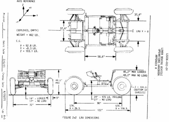
An example of a system that demonstrate legacy is the LRV in Figure
1-1. Three
Lunar Roving Vehicles (LRV) were sent to the moon on
Apollo 15, 16 and 17 with
the specific mission of traversing the terrain of the moon to extend
the operational distance that would otherwise be covered by an
astronaut on foot. Many features were incorporated into each of the
rovers in order to meet the specific demands of the lunar
environment, while making it small and light enough to be
transported to the moon. The
LRV weighed less than the two astronaut passengers. Materials
were chosen that could survive in the lunar environment, it included
specialized power sources, and also barriers that protect from the
regolith. Its
performance characteristics are shown below in Figure 1-8.
1‑8 LRV
performance characteristics (Heiken,
Vaniman, & French, 1991)
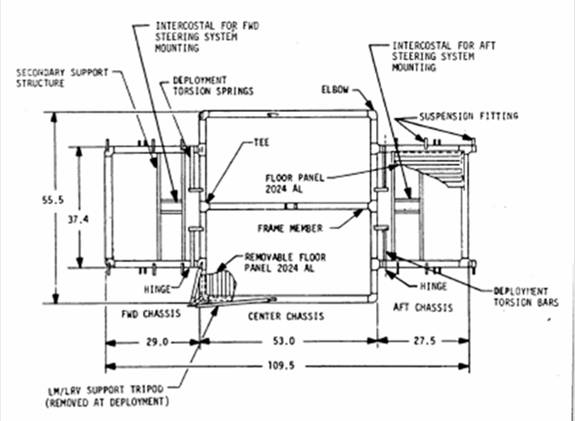
The foldable frame of the LRV (Figure 1-4) was constructed from
Aluminum 2219 tube-welded assemblies. The
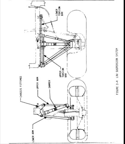
suspension (Figure 1-6) was a double wishbone, each wishbone
attached to a torsion bar and a damper between the chassis and upper
wishbone. The wheels (Figure 1-7) consisted of an aluminum hub, tire
made of zinc coated woven piano wires and titanium chevron treads,
attached to the rim and discs of formed aluminum. Dust
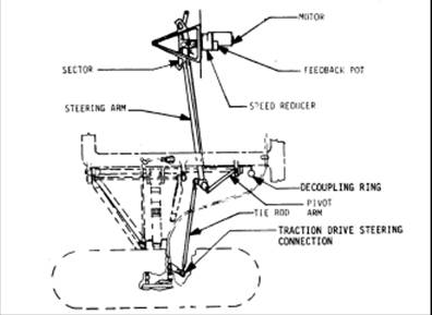
guards were mounted about each wheel in Figure 1-1. Front
and rear wheel steer was accomplished by an Ackermann-geometry
steering linkage system (Figure 1-3), driven by an electric motor
servo-system that amplifies the left and right joystick motion from
the astronaut. The
power system consisted of two 36 V silver-zinc potassium hydroxide
non-rechargeable batteries used to drive four ¼ horsepower electric
motors (Figure 1-5) located at each wheel. This
power system gave the rover an operating range of approximately 57
miles and enabled it to reach speeds up to 17 km/h. The
motors were speed reduced 80:1 with a harmonic drive gearing ( http://www.gearproductnews.com/issues/0406/gpn.pdf ),
which are known for large gear ratios, light weight, compact size
and no gear backlash when compared to a planetary gear system. The
motors and harmonic drive were hermetically sealed and pressurized
to 7.5 psia to protect from lunar dust and for improved brush
lubrication. Braking was both electodynamic by the
motors and from brake shoes forced against a drum through a linkage
and cable. Designed
to carry twice its own weight, the LRV had a clearance of 36 cm when
fully loaded (Figure 1-2).
In order to protect the LRV against the thermal environment of the
moon several different thermal control systems were incorporated
into the LRV design. These systems consisted of MLI blankets
(Multi-layer insulation) covered by Beta Cloth, space radiators,
mass heat sinks, special surface coatings and finishes, and thermal
straps. Most of these components performed well. However one of the
main problems that the LRV encountered was an issue concerning the
lunar dust. Degradation of thermal and electronic components was a
problem as well as the wear and tear of components and other
surfaces from the abrasive lunar dust.
Standards
When reviewing or referencing the following standards, be aware
that they may not have been intended for the lunar environment, so
they may not be entirely applicable in the presence of regolith, and a
different temperature and radiation environment than earth orbit.
· AIAA
S-114-2005, “Moving Mechanical Assemblies for Space and Launch
Vehicles” covers the design of moving mechanical assemblies for
orbit and launch. This
standard “specifies general requirements for the design,
manufacture, quality control, testing, and storage of moving
mechanical assemblies (MMAs) to be used on space and launch
vehicles.” It
considers the mechanical or electromechanical devices that control
the movement of mechanical parts, including gears, lubricants,
bearings, fasteners, springs, dampers
and motors.
· The
Proceedings of the Aerospace Mechanism Symposium are published
annually and papers are concerned with actuators,
lubricants, latches, connectors, and other mechanisms.
· NASA/TP-1999-2069888 NASA
Space Mechanisms Handbook. The
Handbook (including CD/DVD) is available only to US citizens who
need the material. It is
restricted under ITAR (International Traffic in Arms Regulations).
· MIL-HDBK-5
Metallic Materials and Elements for Aerospace Structures, contains
standardized mechanical property design values and other related
design information for metallic materials, fasteners and joints.
Other Standards:
· DOD-HDBK-343
Design, Construction, and Testing Requirements for One of a Kind Space
Equipment
· MIL-STD-100
Engineering Drawing Practices
· MIL-STD-1539
Direct Current Electrical Power Space Vehicle Design Requirements
· DOD-E-8983
General Specification for Extended Space Environment Aerospace
Electronic Equipment
· MIL-S-83576
General Specification for Design and Testing of Space Vehicle Solar
Cell Arrays
· DOD-STD-1578
Nickel-Cadmium Battery Usage
Practice for Space Vehicles
Reference Texts
A number of excellent reference texts are listed in the
References section, including "Space
Vehicle Mechanisms", "Space
Vehicle Design" and "Fundamentals
of Space Systems".
Any hardware or materials used for lunar missions will need to be of
a special variety known as "Flight Qualified". Therefore,
any designer will have at his or her disposal only a limited number
of parts and materials. Care
should always be taken that all materials and parts called out in a
mechanical design are flight qualified. NASA
and commercial spacecraft vendors keep up to date lists of
acceptable materials and components. Any
such list from a reputable source should always be sought at the
start of a mechanical design. Flight
qualified materials and parts are always flight proven hardware with
program heritage. The
process to get any new material or part flight qualified is an
arduous and long task. This
is why most technologies in flight today are 10 to 15 years old. Any
good program manager will choose a flight proven workhorse solution
over a newer, better more exotic technology option. Materials
and parts on spacecraft (and the lunar surface) are exposed to
extreme conditions in space and failures cannot be easily serviced. Therefore,
most programs require all sub-systems to have double or even triple
redundancy in failure threats. For
example, thermostats can fail open or closed and often backup
thermostats are included to take over in the event that the primary
thermostat fails. Any
part that inserts a single point failure in the system is
unacceptable. So
when it comes to mechanical designs for lunar missions, simpler is
better, all parts are flight qualified, and all possible failures
have been identified and fully explored and remedied.
Material selection is strongly affected by the lunar environment,
which can severely degrade material properties. Radiation
will weaken exposed polymeric material, while regolith is very
abrasive and invasive. Material properties can depend
on temperature, for instance carbon steels are not a good choice
because they become brittle at the low lunar temperatures, and
poorly chosen epoxies in composites may soften at high temperatures. The
specific lunar application (temperature, loads, etc.) drives material selection. Hence
a trade study is called for. Below
is attached a portion of a trade study by a student to choose materials for
his
excavator components (excavator bit, structural members, and a
conveyor belt). The student's material choice is
not given.
1.1.1 Aluminum
-
pros: easily machinable, good strength to weight, low cost
-
Applications: frame materials of spacecraft (Conley,
1998), lunar rover frame
-
Among the conventional structural materials, aluminum is by far
the most common. A
large variety of alloys exist providing a broad range of such
characteristics as strength and weldability. Thus,
for applications at moderate temperature in which moderate
strength and good strength-to-weight ratio are desirable,
aluminum is still most often the material of choice. This
popularity is enhanced by ready availability and ease of
fabrication. A
number of surface-coating processes exist to allow tailoring of
surface characteristics for hardness, emissivity, absorbtivity,
etc (Griffin, 1991).
-
Material Properties (MATWEB,
2008) (search:
Aluminum 1199-O)
-
Density: 0.0975 lb/in³
(AA; Typical)
-
Ultimate Tensile Strength: 6530 psi
-
Tensile Yield Strength: 1450 psi
-
Modulus of Elasticity: 8990 ksi
(In Tension; Compressive Modulus is about 2% higher)
-
Poisson’s Ratio: 0.330
-
Shear Strength: 4930 psi
(Calculated value)
-
Shear Modulus: 3630 ksi
-
CTE, linear 20°C: 13.1 µin/in-°F
(20-100ºC)
-
CTE, linear 250°C: 14.2 µin/in-°F
(Average over the range 20-300ºC)
-
Specific Heat: 0.215 BTU/lb-°F
-
Thermal Conductivity: 1690 BTU-in/hr-ft²-°F
-
Melting Point: 1220 °F
-
Material Components:
1.1.2 Beryllium
-
pros: good stiffness, low density
-
cons: machining takes time and care
-
Applications: infrared optics (high reflectivity), precision
gimbal structures (low density & high modulus-to-density ratio),
guidance systems
-
Beryllium offers the highest stiffness of any naturally
occurring material along with low density, high strength, and
high temperature tolerance. Thermal
conductivity is also good. Beryllium
has been used in limited applications where its desirable
characteristics have been required. The
main limitation on more extensive use of this apparently
excellent material is toxicity. In
bulk form, beryllium metal is quite benign and can be handled
freely. The
dust of beryllium or its oxide, however, has very detrimental
effects on the human respiratory tract. This
means that machining or grinding operations are subject to
extensive safety measures to capture and contain dust and chips. This
renders normal fabrication methods unusable without resorting to
these intensive (i.e., expensive) measures [2].
-
Properties (Conley,
1998) pg. 42-46
-
Young’s Modulus: ~303 GPa (-40C to 80C)
-
Poisson’s Ratio: 0.028
-
Tensile Yield: ~265GPa (-40C to 80C)
-
Tensile Strength: 380 to 480 GPa (depending on the grade)
-
Max Service Temp: 750C
1.1.3 Titanium
-
pros: high strength
-
cons: high cost
-
difficult to machine or weld
-
titanium alloys are highly praised for their use in aerospace
and high-temperature applications
-
Titanium is a lightweight, high-strength structural material
with excellent high temperature capability. It
also exhibits good stiffness. Some
alloys are fairly brittle, which tends to limit their
application, but a number of alloys with reasonable ductility
exist. Use
of titanium is limited mostly by higher cost, lower
availability, and fabrication complexity to applications that
particularly benefit from its special capabilities (Griffin,
1991).
-
Properties (MATWEB,
2008)
-
Density: 0.163 lb/in³
-
Ultimate Tensile Strength: 31900 psi
-
Tensile Yield Strength: 20300 psi
-
Modulus of Elasticity: 16800 ksi
-
Poisson’s Ratio: 0.340
-
CTE, linear 20°C: 4.94 µin/in-°F
(over the range 20-100ºC)
-
CTE, linear 1000°C: 5.61 µin/in-°F
-
Specific Heat: 0.126 BTU/lb-°F
-
Thermal Conductivity: 118 BTU-in/hr-ft²-°F
-
Melting Point: 3000 - 3040 °F
-
Emissivity: 0.630 (unoxidized; 650 nm)
1.1.4 Graphite-epoxy
-
pros: lightweight
-
cons: outgassing
-
The use of high-strength and stiffness graphite fiber within an
epoxy matrix offers an excellent high-strength structural
material. Proper
selection of the cloth and/or unidirectional fibers offers the
ability to tailor strength and stiffness directionally and to
the desired levels to optimize it for the purpose. The
low density of graphite offers a weight advantage as well. High-temperature
characteristics are improved by use of graphite instead of
glass, although the matrix is the final limiting factor (Griffin,
1991).
-
Properties (MATWEB,
2008) (search:
Epoxy/Carbon Fiber Composite)
-
Density: 0.0455 - 0.0650 lb/in³
-
Ultimate Tensile Strength: 7250 – 305,000 psi
(Average value: 845 MPa Grade Count:14)
-
Modulus of Elasticity: 1450 – 75,400 ksi
(Average value: 153 GPa Grade Count:14)
-
Compressive Yield Strength: 7250 – 249,000 psi
(Average value: 593 MPa Grade Count:14)
-
Compressive Modulus: 1190 – 17,400 ksi
(Average value: 33.0 GPa Grade Count:5)
-
Shear Strength: 116 - 17400 psi
(Average value: 60.1 MPa Grade Count:9)
-
Flexural Yield Strength: 930 - 18100 ksi
(Average value: 47.2 GPa Grade Count:7)
-
Flexural Modulus: 16000 - 232000 psi
(Average value: 542 MPa Grade Count:7)
-
Thermal Conductivity: 41.6 - 2780 BTU-in/hr-ft²-°F
(Average value: 105 W/m-K Grade Count:9)
-
CTE, linear 20°C: -0.167 - 15.6 µin/in-°F
(Average value: 8.87 µm/m-°C Grade Count:7)
-
Specific Heat: 0.239 - 0.287 BTU/lb-°F
(Average value: 1.13 J/g-°C Grade Count:3)
1.1.5 Stainless
steel
-
cons: weight
-
Applications: structural members, although it is often replaced
by lighter materials, power train components (Conley,
1998)
-
Stainless steel is typically used in applications requiring
higher strength and/or higher temperature resistance. Stainless
is preferred because its use eliminates concern about rust and
corrosion during fabrication and testing. Also,
if the part is exposed to low temperature, the low
ductile-to-brittle (DBT) transition temperature is important (Griffin,
1991).
-
Properties (Conley,
1998) pg. 20-27
-
Properties (Conley,
1998) pg. 230
1.3.1 Linked
metal
-
Not likely feasible – too bulky
1.3.2 Teflon
-
pros: self-lubricated
-
cons: erosion due to radiation
-
Material Properties (MATWEB,
2008) (search: DuPont
Teflon® Grade 30 Aqueous Dispersion)
-
Base Resin Density: 0.0325 lb/in³
(Weight of PTFE resin solids)
-
Specific Gravity: 0.0542 lb/in³
-
Solids Content: 60.0 % (Percent of PTFE resin solids)
-
Particle Size: 0.220 µm
(Average dispersion particle size)
-
pH: 9.50
-
Viscosity: 20.0 cP
(at 25°C)
-
Melting Point: 621 °F
Teflon® PTFE 30 fluoropolymer resin is a negatively charged,
hydrophobic colloid containing approximately 60% (by total weight)
of 0.05 to 0.5 mm polytetrafluoroethylene (PTFE) resin particles
suspended in water. A milky white liquid, Teflon® PTFE 30 also
contains approximately 6% (by weight of PTFE) of a nonionic wetting
agent and stabilizer. Viscosity at room temperature is approximately
20 cP. Nominal pH is 10 (MATWEB,
2008).
Compared with other grades of PTFE dispersions,Teflon® PTFE 30 is a
general-purpose product, often preferred for impregnating woven
goods and for some coating processes. It imparts some of the unique
properties of PTFE resin to porous structures (MATWEB,
2008).
When properly processed, the PTFE resin in Teflon® PTFE 30 exhibits
the superior properties typical of the fluoropolymer resins:
retention of properties after service at 260°C (500°F), useful
properties at –240°C (–400°F), chemical inertness to nearly all
industrial chemicals and solvents, and low friction and antistick
surfaces. Dielectric properties are outstanding and stable with
frequency and temperature (MATWEB,
2008).
Applications:
Teflon® PTFE 30 is used to impregnate packings made from braided
fibers for severe chemical and thermal service; to coat glass fabric
for industrial conveyor belting, nonadhesive separator sheets for
laminating and press blankets, and gaskets; and as surface coatings
for other substrates (MATWEB,
2008).
1.3.3 Glass
Fabric
-
Pros: flexible; can be Teflon coated to improve; lightweight;
can be manufactured for specific properties
-
Cons:
-
Applications: external surface of spacecraft thermal blankets (Griffin,
1991)
-
Fiberglass cloth, which is strong and flexible, has seen use as
an insulator and as protective armor against micrometeoroids. A
commercially available cloth of fiberglass coated with Teflon
called Betacloth has been used as the external surface of
spacecraft thermal blankets for this purpose (Griffin,
1991).
-
Material Properties (MATWEB,
2008) (search:
Industrial Laminates/Norplex NP511 Glass Fabric)
-
Specific Gravity: 0.0650 - 0.0686 lb/in³
(0.062"; ASTM D792)
-
Moisture Absorption at Equilibrium: 0.200 % (0.062"; ASTM
D229)
-
Tensile Yield Strength: 37000 psi
(0.062", CW; ASTM D638) 43000 psi
(0.062", LW; ASTM D638)
-
Modulus of Elasticity: 2700 ksi
(0.062", CW; ASTM D229) 3000 ksi
(0.062", LW; ASTM D229)
-
Flexural Strength: 70000 psi
(0.062", CW; ASTM D790) 80000 psi
(0.062", LW; ASTM D790)
-
Compressive Strength: 63000 psi
(0.5"; ASTM D695)
-
Shear Strength: 22000 psi
(0.62"; ASTM D732)
-
CTE, linear 20°C: 7.22 µin/in-°F
(x-axis (0.062"); IPC-TM 650-2.4.24)
-
CTE, linear 20°C Transverse to Flow: 8.33 µin/in-°F
(y-axis (0.062"); IPC-TM 650-2.4.24)
-
Maximum Service Temperature, Air: 365 °F
-
Glass Temperature: 329 °F
(Tg)
-
Flammability, UL94: HB (0.062")
-
Bond Strength: 2200 lb (0.5", ASTM D229)
-
Color: Natural
1.3.4 Kapton
tape
-
Applications: outer layers of thermal blankets (Griffin,
1991)
-
A new polymeric film material with higher strength and the
ability to withstand higher temperature than Mylar is the
polyimide Kapton. These
characteristics have made Kapton a desirable choice for outer
layers of thermal blankets. A
problem has arisen with the discovery that, in low Earth orbits,
polymer surfaces undergo attack and erosion by atomic oxygen,
which is prevalent at these altitudes. Kapton seems
to be more susceptible to this sort of attack than Mylar. In
any case, for long life use in low orbit, metallization or
coating with a more resistive polymer such as Teflon will
probably be required. This
erosion rate is sufficiently low that, for shorter missions, the
problem may not be serious (Griffin,
1991).
1.3.5 Mylar
-
Application: MLI on spacecraft (Griffin,
1991)
-
By far the most commonly used plastic film material in space
applications has been Mylar. This
is a strong, transparent polymer that lends itself well to
fabrication into sheets or films as thin as 0.00025 in. Coated
with a few angstroms of aluminum to provide reflectivity, Mylar
is well suited to the fabrication of the multilayer insulation
extensively used on spacecraft (Griffin,
1991).
1.4.1 Hardened
steel
1.4.2 Diamond
-
pros: high hardness
-
cons: cost, brittle failure
-
Material Properties (MATWEB,
2008)
-
Density: 0.108 - 0.145 lb/in³
-
Compressive Yield Strength: 1900 - 6900 MPa
-
Poisson’s Ratio: 0.0700 - 0.200
-
Thermal Conductivity: 8330 BTU-in/hr-ft²-°F
(Thick film diamond made by SP3)
-
Thermal Conductivity: 12500 BTU-in/hr-ft²-°F
(De Beers thermal thick film synthetic diamond)
-
Fracture Toughness: 5.46 - 8.01 ksi-in½
1.5.1 AISI
440C Stainless Steel
-
Application: typically used in space mechanism bearings (Conley,
1998)
-
heat treatable
-
high wear resistance
-
moderate corrosion resistance in mild environments
-
Material Properties (MATWEB,
2008)
-
Density: 0.282 lb/in³
-
Ultimate Tensile Strength: 254000 psi
-
Tensile Yield Strength: 186000 psi
-
Modulus of Elasticity: 29000 ksi
-
Charpy impact: 14.0 ft-lb
-
CTE, linear 20°C: 5.67 µin/in-°F
(from 32-212°F)
-
Specific Heat: 0.110 BTU/lb-°F
(from 32-212°F)
-
Max service temp, air: 1400 °F
(Continuous Service); 1500 °F
(Intermittent Service)
-
Material Components:
-
Carbon, C 0.600
- 0.750 %
-
Chromium, Cr 16.0
- 18.0 %
-
Manganese, Mn <=
1.00 %
-
Molybdenum, Mo <=
0.750 %
-
Phosphorous, P <=
0.0400 %
-
Silicon, Si <=
1.00 %
-
Sulfur, S <=
0.0300 %
None
1.7.1 Outgassing
concerns
-
(Conley, 1998) pg.
224
-
Most composite materials will outgas their volatile content when
taken into a low pressure environment
1.7.2 Other
Issues
-
Some temperature ranges are given for the material properties
above as well as operable temperatures in sources
-
No data is available on Mylar, Kapton, etc., other than the
general information.
-
Most of the structure will be built from aluminum, while the bit
will be comprised of stainless steel
-
Efforts were made to select materials that are used in space
applications (space rated).
Space Fasteners design choices, with attention given to aerospace
applications, materials and temperature ranges, are presented in the
Fastener Design Manual (Barrett,
1990),http://gltrs.grc.nasa.gov/reports/1990/RP-1228.pdf. The
document considers fastener material selection, platings,
lubricants, locking methods, washers, inserts, rivets and lockbolts,
and bolthead markings and design data tables. Design
calculations for loading conditions is also presented, including
fatigue loading, fastener torque, combined shear and tension loads,
pullout load for tapped holes, grip length, head styles, and
fastener strengths. MIL-HDBK-5
also contains allowable strengths for many fasteners. Fasteners
for MS (military standard) and NAS (national aerospace standard) can
be found athttp://www.standardaeroparts.com/.
From the table in Figure 1-9, notice that carbon steel bolts have a
limited temperature range, becoming brittle at -65F. The
stainless steel bolts appears offer a range of choices that may be
acceptable for lunar machinery.
From the table in Figure 1-10, cadmium is the most common. Zinc
coatings can be considered if expected temperatures do not exceed
the limit.
From the table of Figure 1-11, molybdenum disulfide is most
appropriate for the temperature and vacuum conditions as a thread
lubricant.
1‑9 Fastener
materials, from (Barrett,
1990)
1‑10 Fastener
platings and coatings (Barrett,
1990)
1‑11 Thread
lubricants, from (Barrett,
1990)
Rolling-element bearings for lunar applications must capably
withstand the challenges of the lunar environment (temperature
extremes, penetrating regolith and the vacuum environment) and be
highly reliable to minimize repairs. If
not hermetically sealed they will be subject to vacuum pressures. Temperature
extremes could induce thermal stresses and thermal distortions. Significant
loads and vibrations often occur during launch are also a concern. For
space flights the AISI 440C (a high hardness, corrosion resistant
steel) and AISI 52100 (not as hard or corrosion-resistant as AISI
440C, but better wear resistance) are the most common. Hybrid
bearings, a combination of ceramic ball and metallic race, reduce
micro-welding at ball and race contact, may have advantages in some
situations.
Shields and seals cover the rolling element so they are not exposed
and protected to a certain degree from outside contaminates like
regolith. Shields
and seals are attached on a bearing’s outer race, and move with the
outer race. A
shield will not touch the inner race because of a small clearance
gap. Seals
do rub against the inner race but will be less likely to allow
regolith particles inside. Thermal
control is a concern in a lunar environment where convection is not
an available heat transfer mechanism. Thermal
conductivity through a bearing is increased by the presence of a
lubricant.
Lubricant inadequacies have been
implicated as a cause of a number of space mechanism failures. An
ideal lubricant would retain the desired viscosity over a wide
temperature range and be nonvolatile. The
ability of a lubricant to resist becoming a gas is related to its
molecular weight. Low
molecular weight lubricants are more volatile in vacuum and heat
than higher molecular weight lubricants. The
three types of lubricants are liquids (lubricating oils, lubricant
greases) and solid films. Fluorinated
oils and greases have excellent vacuum characteristics. Solid
films, such as soft metal films, polymers and low-shear strength
materials, find use in bearings, bushings, contacts and gears. See (Conley,
1998) and (Fusaro,
1994) for details.
A motor is considered to be a component in a system hierarchy. The
types that have been used in satellites include DC brush, DC
brushless and stepper motors. Below
is a trade study performed by a student, comparing different motor
types for a lunar excavator conveyor, rated for 100W available DC power.
The student's recommendations and conclusions are included, however
they have not been verified. You will need to do your own
trade study.
DC- Brush Motor
- Operation
of brushed motor at reduced atmospheric pressures cause the motor to
fail prematurely due to brush wear
- In
general the longest brush life for a motor occurs under room ambient
conditions
- Brush
wear is dependent of brush material, motor design, and operating
loads
- Slow
speed torque motors have good life, usually more expensive
- Samarium
Cobalt: Operating, Tmax 300-330 deg C without damage
- On
Earth moisture in the air helps to lubricate the brushes of the
motor, in a vacuum there is no moisture to lubricate the brushes of
the motor, which is the main reason for brush wear.
- RECOMMENDATION-
To find alternatives to brush motor because of short life, and high
costs. For the conveyor the motor is running almost continually thus
wearing down the brushes at an accelerate rate.
DC- Stepper Motor
- Natural
companion for occasional duty, moderate rates and frequently precise
pointing accuracy
- This
type of motor was used on Surveyor Lander in the 1960’s
- Has
the capability to be directly driven by a digital processor, and
runs of traditional DC power
- Attractive
in applications where power is limited
- Has
high, detent torque, which allows the motor to be held in position
without power. Detent torque is approximately 85% of powered torque
- Hybrid
stepper motor produces most torque for a given diameter and length
- Almost
all heat losses occur in the stator, so should have a good
conduction path to other structures
- RECOMMENDATION-
Both the stepper and stepper hybrid motors are an attractive
option for this project. Since power is limited for the lunar
excavator a stepper motor would be a more sensible choice. Also
the motor can be digitally-controlled which would allow easy
control from earth.
DC-Brushless Motor
- Most
versatile general purpose of the electric motors
- Windings
are switched or communicated electronically rather than mechanically
- Internal
permanent-magnetic field is trapezoidal shape for max torque and
smooth rotation
- Careful
thermal design can increase motor’s capacity
- RECOMMENDATION-
DC Brushless may be an appropriate option because of its versatility
and ability for continual use. With high torque capability it may
provide the best solution to run the conveyor belt. Thermal concerns
can be reduced with a precision design of the motor.
Final Choice
The final choice for the space-qualified motor was a stepper motor. The specific motor is:
Phyrton Vacuum Sealed Stepper Motor, model VSH 125.200.10
Please see appendix for detailed specifications. This motor was
chosen because, despite having a max power rating above the allotted
100 watts the motor could operate at the power output of 37.7 watts
(1/20 HP). 37.7 watts was the power rating on the first generation
excavator.
Below is a trade study performed by a student to select a power system for a lunar excavator.
You will need to perform your own trade study.
Basic
Components of a Spacecraft Power System (Patel,
2004), (Gilmore, 2002)
Selection of a power system is based primarily on low mass and low
cost components.
-
Primary Energy Source – Solar
radiation, radioisotopes, nuclear reactors, electrochemical
and/or chemical fuel.
-
Energy Conversion – Photovoltaic,
thermoelectric, dynamic alternator, fuel cell and thermo-ionic.
-
Power Regulation & Control – Battery charge
and discharge converters, shunt dissipators, mode controller for
bus voltage error signal
-
Rechargeable Energy Storage – Rechargeable
batteries (Silver Zinc, Nickel Cadmium, Nickel Hydrogen, Nickel
Metal Hydride, Lithium Ion).
-
Distribution & Protection – Structure
to protect vital electrical components from the space
environment.
Primary Energy Source
A primary energy source is applicable for low power, short-life
satellites and spacecraft. After
the battery is drained, it is typically jettisoned for mass
reduction. Therefore,
the primary energy source will be replaced by a rechargeable energy
source for a longer life span.
Energy
Conversion
The most widely used and cost efficient form of energy conversion is
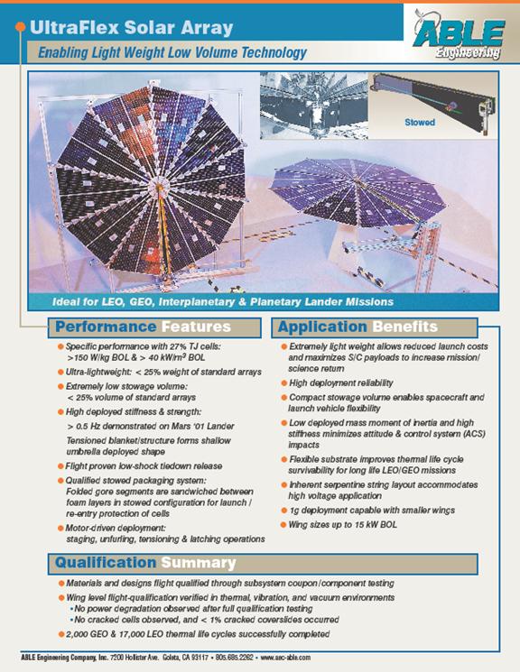
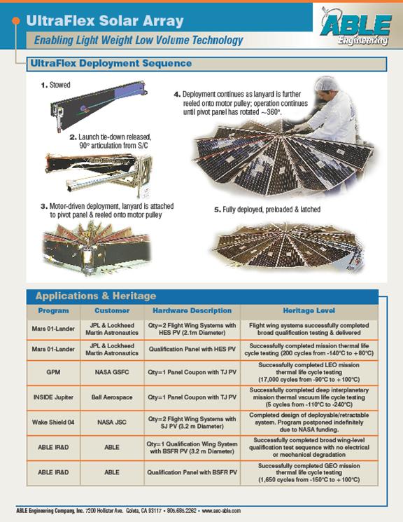
the photovoltaic solar array. Solar
arrays can provide power requirements from tens of watts to several
kilowatts with a life span of a few months to fifteen years. After
fifteen years, the life of a solar array degrades due to the space
environmental effects on the photovoltaic cells. Ionized
particles, micrometeoroid impact, debris and ultraviolet radiation
are concerns when designing solar arrays. A
method to protect against radiation effects and to enhance solar
energy absorption is to layer the array with fused silica or
ceria-doped microsheet coated with silica monoxide. Single-crystal
silicon, gallium arsenide, semi-crystalline and poly-crystalline,
thin film, amorphous and multi-junction are types of photovoltaic
cells used in the space environment.
-
Single-Crystal Silicon Cells
-
Advantage: Widely
available and have been used as the “workhorse” of the space
industry
-
Disadvantage: Expensive
manufacturing process for space qualified cells
-
Gallium Arsenide Cells
-
Advantage: High
conversion efficiency in comparison Single-crystal Silicon
cells
-
Disadvantage: Extremely
expensive to manufacture
-
Semi-Crystalline & Poly-Crystalline Cells
-
Advantage: Low
cost of manufacture which gives a net reduction in the cost
per watt
-
Disadvantage: Low
energy conversion efficiency
-
Thin Film Cells
-
Advantage: Less
expensive to manufacture
-
Disadvantage: Has
not been used widely in space applications (lack of data).
-
Amorphous Cells – Not enough data to be selected as a serious
candidate for space applications (new technology).
-
Multi-Junction Cells – High efficiency and good
manufacturability.
Power Regulation & Control
Power regulation and control is necessary in monitoring battery
health and preventing over charge and discharge because batteries
may be susceptible to damage. Power
regulation also includes the incorporation of shunt dissipators to
dissipate power that is unwanted after meeting the load power and
the battery charge requirements. Thermal
requirements for electrical components can also be contained in the
power regulation and control because batteries and associated
components typically require certain temperature operating ranges to
perform efficiently.
Rechargeable Energy Sources
-
Silver Zinc Batteries – Although Silver Zinc batteries have a
high specific energy, they consist of a low cycle life and are
not suitable for lunar excavation applications.
- Nickel Cadmium (NiCd)
- Advantages:
- Responsible for powering all satellites until
mid-1980s
- Disadvantages:
- Low specific energy
- Temperature sensitive (Operating range: 0-10°C)
- Short life cycle
- Cadmium is under environment regulatory scrutiny
- Nickel Hydrogen (NiH2) – Currently used in place of
Nickel Cadmium for space applications.
- Advantages:
- Most widely used in space applications in the last 20
years
- Selected for use in the International Space Station
- Can withstand some abuse due to overcharge and over
discharging
- Superior charge/discharge life cycle compared to Nickel
Cadmium
- Low internal resistance
- Internal pressure can be measured by a mounting a strain
gage on pressure vessel
- Disadvantages:
- Low energy density
- Pressure vessel rupture, handling and safety concerns
- Compression seal is typically coated with Teflon
resulting in poor radiation tolerance in certain space
applications
- High self discharge rate
- Temperature sensitive (Operating range: 0-20°C) – Adds
mass to thermal control system
- High loss of capacity on storage
- Large support structure for battery systems (Increased
mass)
- Nickel Metal Hydride (NiMH)
- Advantages compared to NiCd:
- Electrode materials are non-toxic
- Improvement in specific energy
- Negligible memory effect
- Advantages compared to NiH2:
- Less sensitive to temperature – Lower thermal control
cost
- Improved energy density
- Less support structure
- Lower operating pressure
- Disadvantages:
- Less capable of producing high peak power
- High self discharge rate
- Adversely affected by high temperatures
- Susceptible to damage due to overcharging
- Very expensive
- Few space applications use NiMH batteries
- Lithium-Ion (Li-Ion)
- Advantages:
- Higher specific energy and energy density than NiH2
- High charge efficiency
- Potentially long cycle life at high depth of discharge
- Low temperature sensitivity
- Low internal impedance
- Capable of delivering high short time peak power
- Small battery footprint
- Disadvantages:
- Sensitive to overcharge and over discharge – Requires
more elaborate charging circuitry with adequate
protection
- Requires trickle charging
Protection
The most common form of protection of electrical components and
batteries is the design and construction of a “battery box” type
structure to house all the components. The
structure is typically built out of aluminum or a similar type space
rated material. To
protect against radiation, a MLI (Multilayer insulation) material is
placed around the structure as a barrier. MLI
serves a dual purpose by preventing excess heat loss from a
component and by preventing excessive heating to a component from
environmental fluxes. The
simplest type of MLI is assembled from thin embossed Mylar sheets
with a layer of aluminum on one side. More
efficient designs include the material Kapton. Thermal
design of the spacecraft primarily uses resources in the environment
for heating and cooling needs. However,
in severe environments or extremely sensitive components, auxiliary
insulators, heaters, radiators or louvers may be used to maintain
operational temperatures.
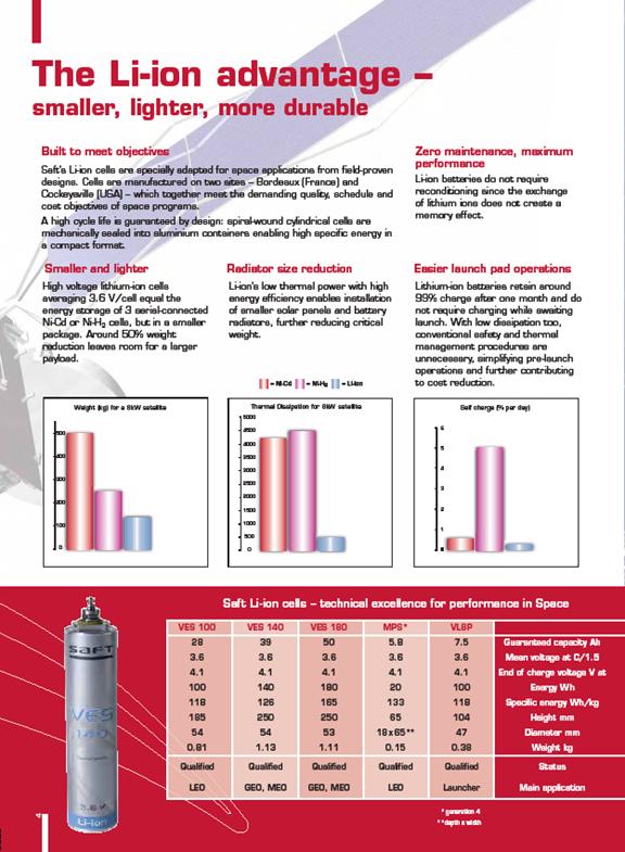
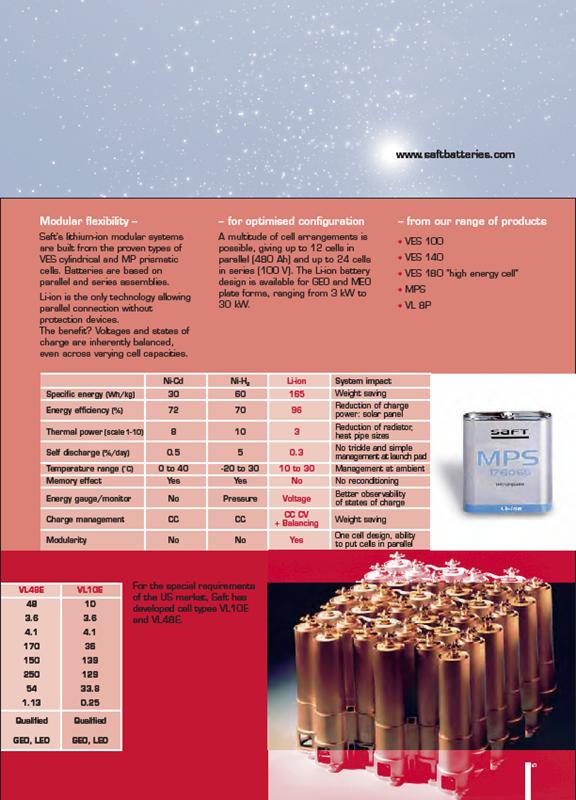
Recommendations
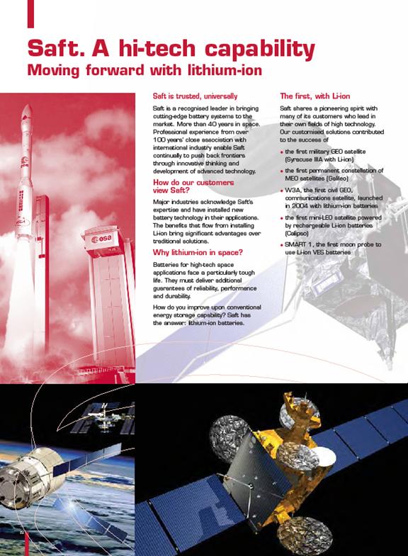
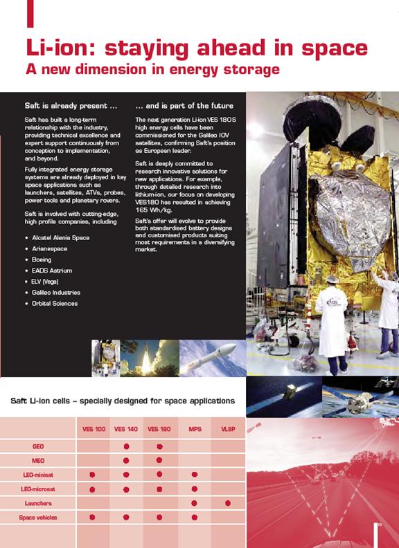
Battery –
Lithium Ion (Saft Battery Group) – See attached industrial brochure.
For the lunar excavator, the best choice for a rechargeable battery
is the Lithium Ion. The
main disadvantage of the Lithium Ion is the sensitivity to
overcharging and over discharging. This
can be dealt with by the implementation of an acceptable power
regulation and control system. The
Lithium Ion is also a good choice for the excavator power system
because of mass requirements. Li-Ion
batteries do not require a great deal of space and therefore the
mass of the system can be reduced. Lithium
Ion batteries are currently being used on the Mars Rover for
approximately 4.5 years (Halpert,
1999).
Solar Cells/Array (Able Engineering) – See industrial brochure in
the Appendix
Barrett, R. T. (1990). Fastener
Design Manual: NASA Lewis Research Center.
Conley, P. L. (Ed.). (1998). Space
Vehicle Mechanisms: Elements of a Successful Design: John Wiley
& Sons.
Eckart, P. (1999). The
Lunar Base Handbook: McGraw-Hill.
Fusaro, R. L. (1994). Lubrication
of Space Systems. Paper
presented at the Society of Tribologists and Lubrication Engineers
Annual Meeting.
Gies, J. (1996). The
Effects of the Lunar Surface upon Machinery. Paper
presented at the Proceeding of Space 96.
Gilmore, D. G. (Ed.). (2002). Spacecraft
Thermal Control Handbook, Volume 1: Fundamental Technologies (2nd
ed.): The Aerospace Corporation.
Griffin, M. D., French, J.R. (1991). Space
Vehicle Design: AIAA Education Series.
Halpert, G., Frank, H., Subbarao, S. (1999). Batteries and Fuel
Cells in Space. The
Electrochemical Society Interface, 25-30.
Heiken, G. H., Vaniman, D. T., & French, B. M. (Eds.). (1991). Lunar
Sourcebook A User's Guide to the Moon: Cambridge University
Press
LPI. (2008a). Lunar and Planetary Institute Website. from http://www.lpi.usra.edu/
LPI. (2008b). Lunar and Planetary Institute Website: The Apollo
Roving Vehicle. from http://nssdc.gsfc.nasa.gov/planetary/lunar/apollo_lrv.html
MATWEB. (2008). MatWeb - Material Property Data from http://www.matweb.com/
NASA. (1971). Lunar
Roving Vehicle Operations Handbook LS0006-002-2H.
NASA. (2007). Systems
Engineering Handbook, NASA/SP-2007-6105 Rev1
NASA Headquarters, Washington, D.C., 20546.
Patel, M. R. (2004). Spacecraft
Power Systems: CRC Press.
COTS solar panels and batteries.