Xiao Qin's Research
Annual Report
BUD: A Buffer-Disk Architecture for Energy Conservation in Parallel Disk Systems
Download BUD Annual Report PDF
Findings
An Energy-Efficient Framework for Large-Scale Parallel Storage Systems
A Simulation Framework for Energy-efficient Data Grids
An Energy-Efficient Scheduling Algorithm Using Dynamic Voltage Scaling
for Parallel Applications on Clusters
Load-Balancing Strategies for Energy-Efficient Parallel Storage Systems with Buffer Disks
Sacrificing Reliability for Energy Saving: Is It Worthwhile for Disk Arrays
Load-Balancing Strategies for Energy-Efficient Parallel Storage Systems with Buffer Disks
Energy-Efficient Prefetching for Parallel I/O Systems with Buffer Disks
Improving Reliability and Energy Efficiency of Disk Systems via Utilization Control
Energy Conservation for Real-Time Disk Systems with I/O Burstiness
An Adaptive Energy-Conserving Strategy for Parallel Disk Systems
DARAW: A New Write Buffer to Improve Parallel I/O Energy-Efficiency
MICRO: A Multi-level Caching-based Reconstruction Optimization for Mobile Storage Systems
PEARL: Performance, Energy, and Reliability Balanced Dynamic Data Redistribution for Next Generation Disk Arrays
HyBUD: An Energy-Efficient Architecture for Hybrid Parallel Disk Systems
Energy-Aware Prefetching for Parallel Disk Systems
DORA: A Dynamic File Assignment Strategy with Replication
Collaboration-Oriented Data Recovery for Mobile Disk Arrays
A File Assignment Strategy Independent of Workload Characteristic Assumptions
References
A focus of the research activities carried out in the last year is the design of an energy efficient parallel disk architecture for inter-request parallelisms.
The architecture consists of four major components: a RAM buffer, m buffer disks, n data disks, and an energy-aware buffer-disk controller. The new BUD disk architecture is diagramed below [Zong et al., 2007]:
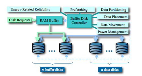
The RAM buffer with a size ranging from several megabytes to gigabytes is residing in the main memory. The buffer-disk controller carefully coordinates energy-related reliability model, data partitioning, disk request processing, data movement/placement strategies, power management, and prefetching schemes. Please refer to Section 3 for details of how the controller will be designed and developed. We choose to use log disks as buffer disks, because data can be written onto the log disks in a sequential manner to improve performance of disk systems. It is to be noted that in most cases, the number of buffer disks m is smaller than the number of data disks n, and values of m and n are independent of one another for workloads with inter-request parallelisms.
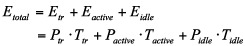
We introduced a model to calculating energy consumption for disk drives in a parallel disk system. [Zong et al., 2007a] The basic power model for this study is a summation of all power states multiplied by the time each power state was active. The states used are start-up, idle, and read/write/seek. Read, write and seek are put together, because they share similar power consumption. Let Ttr be the time required to enter and exit the inactive state. The power consumption of a disk when entering and exiting the inactive state is Ptr. Thus, energy Etr consumed by the disk when it enters and exits the inactive state is expressed as PtrTtr. Similarly, let Tactive and Tidle are the time intervals when the disk is in the active and inactive states, respectively. We denote the energy consumption rates of the disk when it is active and inactive by Pactive and Pidle, respectively. Hence, the energy dissipation Eactive of the disk when it is in the active state can be written as , and the energy Eidle of the disk when it is sitting idle can be expressed as PidleTidle. The total energy consumed by the disk system can be calculated as
Let Tai and Tia denote times a disk spends in entering and exiting the inactive state, Pai and Pia are the power consumption rates when the disk enters the inactive and active states. Let Nai and Nia be the number of times the disk enters and exits the inactive state. Then, the transition time Ttr and power Ptr can be computed as follows

In most cases where the values of Nai and Nia are both equal to Ntr, Ttr can be written avs

The time interval Tactive when the disk is in active state is the sum of serving times of disk requests submitted to the disk system.
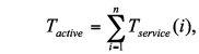
where n is the total number of submitted disk requests, and Tservice(i) is the serving time of the ith disk request. Tservice(i) can be modeled as

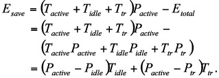
where Tseek is the amount of time spent seeking the desired cylinder, Trot is the rotational delay and Ttrans is the amount of time spent actually reading from or writing to the disk. Now we quantify energy saved by power management policies as below
[Zong et al., 2007a] Write requests can be divided into small write requests and large write requests. Whenever the controller receives a write request, it will first check the size. If the request is a large write, say over 10MB or more, it is sent directly to the corresponding data disk. Otherwise, the controller will send this request to the RAM buffer that buffers small writes from the host and form a log of data to be written into one of the buffer disks later. Once the data are transferred to the RAM buffer, the controller will send a “write complete” acknowledgement message to the sender. Then the controller will test the state of all the buffer disks. If one buffer disk is not busy with writing a previous log or reading or transferring data, the data copy will be sent to this buffer disk to ensure that a reliable copy resides on one of the buffer disks. In order to guarantee the correctness and consistency of different data version, the controller is always trying to match the data with same block to the same buffer disk unless it is known that the data block is already outdated. In other words, operations which could write the same block data into different buffer disks is forbidden if one legal copy of this block still exists in any buffer disk. The most important scheduling strategy between RAM buffer and buffer disk is that rather than wait until the RAM is full, the data are written into the buffer disks whenever they are available. This policy has two major advantages. First, data re guaranteed to be written into one of the reliable buffer disks in the shortest time period, which is very important to ensure the reliability and availability of data. Second, the RAM buffer can have more available room to buffer a large burst of new requests because previous data are always quickly moved from the RAM to the buffer disks. Here we should note that the total storage space of each buffer disk is divided into equal n parts (n is the number of data disks) which are used to buffer the data requests corresponding to each data disk. For example, if we have two 10GB buffer disks and ten 100GB data disks, each buffer disk will have 1GB as the buffer space for each data disk. All the small write requests to data disk 1 will be buffered in the corresponding buffer space reserved for disk 1. The reason we split the buffer disks into small pieces for each data disk is to improve the response performance of the whole system. In the case when one buffer disk is busy writing or moving data, the other disk could serve the incoming requests immediately.