New Criteria Recommended for Designing Perpetual Pavements
Long-life or perpetual pavements are designed and built to last longer than 50 years, requiring only a periodic mill and inlay of the surface layer. The pavement structure is designed using appropriate materials and layer thicknesses to prevent structural distresses that begin at the bottom of the pavement structure, such as bottom-up fatigue cracking and subgrade rutting. To eliminate deep structural distresses, horizontal tensile strains at the bottom of the asphalt layer and vertical compressive stresses/strains at the top of the subgrade must be less than critical thresholds at which damage begins to occur. Additional asphalt thickness above what is required to keep stresses/strains below the critical thresholds is unnecessary to ensure long life. Thus, the goal of perpetual pavement design is to optimize layer thicknesses to sustain heavy loads indefinitely without being overly conservative. Asphalt thicknesses for perpetual pavements have typically ranged from 9 to 16 in. depending on traffic, materials, and site conditions.
Refining Limiting Strain Criteria for Perpetual Pavement Design
NCAT recently completed a NAPA-sponsored study to improve the cost-effectiveness of long-life pavements by establishing critical design thresholds and approximate ranges of maximum thickness. Existing literature was reviewed to determine historical parameters used in perpetual pavement design. To prevent bottom-up fatigue cracking, perpetual pavements have typically been designed so that tensile strains at the bottom of the asphalt structure are less than the fatigue endurance limit (FEL) of the asphalt mixture in the bottom layer. Typical values for the FEL range from early, conservative estimates of 70 microstrain up to more recent values of 200 microstrain. To prevent structural rutting, a vertical strain limit of 200 microstrain at the top of the subgrade has been proposed.
A previous analysis of pavement response data from instrumented sections at the NCAT Test Track showed poor correlations between laboratory FELs and field fatigue cracking performance or field-measured strains. Instead, cumulative field-measured strain distributions and fatigue ratios (cumulative strains divided by the FEL of the asphalt base layer) were found to better predict bottom-up fatigue cracking. Due to these promising results, another detailed analysis was conducted to refine the approach using PerRoad, a mechanistic-based pavement design and analysis program.
Six test sections built in the 2003 and 2006 Test Track research cycles were simulated in PerRoad to predict strain values at the bottom of the asphalt structures. Three sections were deemed perpetual without any bottom-up cracking, and the other three sections experienced bottom-up fatigue cracking. The predicted strain values were then used to develop a limiting cumulative strain distribution and maximum fatigue ratios, which clearly separated the perpetual pavement sections from the others.
The refined limiting strain distribution and maximum fatigue ratios were then validated using data from six sections constructed for the 2009 Test Track research cycle. As before, cumulative strain distributions and fatigue ratios determined by PerRoad simulations failed both limiting cumulative strain distribution and maximum fatigue ratios. All six sections experienced bottom-up fatigue cracking, and comparisons with the design limiting strain distribution accurately characterized all six sections.
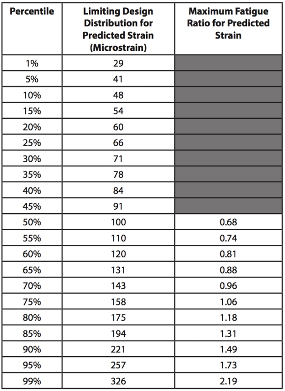
Table 1 presents the limiting cumulative strain distribution and fatigue ratios refined in this study for future use in perpetual pavement design instead of a conservative limiting strain of 70 microstrain or the laboratory FEL of the asphalt base layer.
Table 1: Refined Limiting Strain Distribution and Maximum Fatigue Ratios for Predicted Tensile Strain
Estimating Ranges of Maximum Pavement Thicknesses
Based on the refined limiting strain criteria, an analysis was conducted using PerRoad simulations to determine ranges of maximum pavement thickness. The analysis included three climatic conditions and incorporated a conservative traffic level within legal load limits for various subgrade and base moduli combinations. The procedure was similar to that conducted in SHRP 2 Project R23 (although this used the new limited strain criteria) and included entering structural information and loading conditions, running the PerRoad simulation, and extracting the output data to compare against the limiting criteria in Table 1. The full procedure is listed in NCAT Report 15-05.
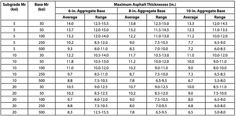
For the pavement to pass, the cumulative tensile strain distribution at the bottom of the asphalt needed to be less than that presented in Table 1, and the vertical compressive strain distribution at the top of the subgrade needed to have at least 50% of values below 200 microstrain. If the pavement failed either of these criteria, the AC thickness was adjusted and the design was repeated. The resulting approximate ranges of maximum design thicknesses for asphalt pavements are shown in Table 2. Depending on site-specific conditions, the range of approximate maximum asphalt thickness was between 5 and 15.5 in.
Table 2: Ranges of Maximum AC Thicknesses
Recommendations for Implementation
The limiting cumulative strain distribution was found to be the best indicator of how the structural test sections resisted bottom-up fatigue cracking at the NCAT Test Track. Based on these findings, the limiting cumulative strain distribution and fatigue ratios in Table 1 are recommended for use in perpetual pavement design instead of a conservative limiting strain of 70 microstrain or the laboratory FEL of the asphalt base layer.
Approximate ranges of maximum AC thicknesses for flexible pavement design are provided in Table 2. A similar table can be developed on a state-by-state basis based on the methodology presented in this study (detailed in NCAT Report 15-05) to represent specific climate, material, and subgrade conditions.
When the thickness of a new or rehabilitated pavement designed based on agency-specific methodology is greater than the maximum thickness, the perpetual pavement design approach may be used to optimize a design that can sustain the heaviest loads and provide an indefinite structural life without being overly conservative.