- National Center for Asphalt Technology
- Field-Based Fatigue Ratios for Perpetual Pavement Design
Field-Based Fatigue Ratios for Perpetual Pavement Design
Perpetual pavements are designed and built to last for more than 50 years, requiring only a periodic mill and inlay of the surface layer. The benefits of building such long-lasting pavements include low life-cycle costs, low user-delay costs and reduced environmental impacts. One aspect of designing perpetual pavements is the prevention of fatigue cracking by limiting the horizontal strain at the bottom of the hot-mix asphalt (HMA) layer. An appropriate strain or fatigue endurance limit must then be determined so that the pavement structure can be cost-effectively designed to avoid fatigue damage.
Laboratory tests, such as the bending beam fatigue test, generally underestimate fatigue life in the field. Thus, engineers apply a shift factor, ranging from 4 to 100, to better relate lab results to field fatigue life. A commonly used fatigue threshold for flexible pavement design is 70 microstrain, a value based on laboratory testing at one temperature. However, results from the NCAT Pavement Test Track have shown that pavements can withstand higher strain levels in the field, indicating that flexible pavements can be designed thinner without sacrificing fatigue life.
Structural sections from the 2003 and 2006 test track cycles have provided pavement response and performance data to aid in determining field-based strain criteria for perpetual pavement design.
2003 Fatigue Study
Two asphalt base mixtures from the 2003 test track cycle were evaluated in the laboratory using the bending beam fatigue test, AASHTO T 321, to determine their fatigue endurance limits. The mixes were identical except for binder grade and were placed in seven structural sections, with total HMA thickness varying from five to nine inches. A total of 10 million equivalent single axle loads (ESALs) were applied in the two-year research cycle. During that time, pavement strain data were collected through embedded instrumentation and weekly performance surveys were conducted.
Initial attempts to relate laboratory fatigue thresholds and field-measured strains were unsuccessful. In the first analysis, field-measured strain-temperature relationships were developed to compare field strain at 20°C—the temperature at which lab beam fatigue testing is conducted—to the lab fatigue endurance limit. However, no clear relationship could be determined. A second analysis technique involved superimposing the lab fatigue endurance limit on cumulative strain distributions from the start of trafficking until fatigue cracking became evident. Although it would seem that sections with a higher percentage of strain events below the lab fatigue endurance limit would be more fatigue-resistant, this was not always the case. Sections N2 and N6, both of which experienced cracking, had higher percentages of strain events below the fatigue threshold than section N3, which did not crack. However, it was observed that sections with fatigue cracking had wider strain distributions, and thus, higher overall strains, than sections that did not crack.
A third attempt to relate laboratory fatigue thresholds and field-measured strains gave much better results. This method compared the entire cumulative strain distribution to the laboratory-determined fatigue threshold, using the concept of fatigue ratios. A fatigue ratio at a given percentile is defined as the ratio of strain at that percentile to the lab fatigue threshold. Among the 2003 structural test sections, a divergence was observed between the fatigue ratios of sections with fatigue damage and those without. From the 60th to the 99th percentile, the fatigue ratios of sections that cracked were distinctly higher than those that did not crack.
2006 Fatigue Study
Eleven sections—varying in HMA thickness from 7 to 14 inches and including a range of mixtures—comprised the 2006 structural study at the Test Track. Of the eleven sections, six were new construction. Sections N3, N4, N6 and N7 remained in-place from the previous cycle of testing, while the existing section N5 received a two-inch mill and inlay to mitigate top-down surface cracking. As trafficking progressed, the strain analyses were discontinued for two of the new sections due to cracking; the distress was later shown to be surface cracking, not fatigue-related.
Beam fatigue testing was conducted for each of the three new base mixtures. Six beams were compacted for each mixture at an air void content of 5.5 percent to reflect the in-place density of the mixes placed on the track. This differed from the 2003 beam fatigue testing, in which the specimens were compacted to 7 percent air voids. The beams were tested at 20°C and a frequency of 10 Hz; half of the specimens were tested at a controlled strain of 800 με, and the other half were tested at 400 με. While the two base mixes from 2003 had similar fatigue results in the lab, the lab fatigue results among the 2006 base mixes were much more diverse.
Field-measured strains were collected through embedded pavement instrumentation. The analysis excluded strain readings after evidence of fatigue damage for any section, as a pavement structure ceases to be perpetual when fatigue cracking occurs.
As with the analysis of the 2003 data, no clear relationship was found between the laboratory fatigue endurance limit, field strains at a normalized temperature and field performance. The second analysis technique, superimposing the lab fatigue endurance limit on the field cumulative strain distribution, yielded results that were more intuitive than with the 2003 data, but were impractical as design criteria. As with the 2003 study, the fatigue ratio concept proved to be the most successful means of relating lab and field fatigue results.
Recommendations
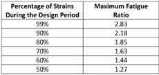 Rather than a single limiting strain criterion, the researchers recommend maximum allowable fatigue ratios, shown in Table 1, for perpetual pavement design. The analysis included multiple sections from the 2003 and 2006 cycles that did not experience fatigue cracking. These limits reflect the section that had the highest fatigue ratios. These results are based on laboratory fatigue testing of beams compacted to 7 percent air voids.
The maximum fatigue ratios can be used to determine an allowable strain distribution by multiplying the fatigue ratio by the 95th percentile confidence interval lower bound endurance limit for a mixture. Further analysis of the fatigue ratio concept is being conducted using base mixtures from the 2009 Test Track.
For More Information
The full report, Field-Based Strain Thresholds for Flexible Perpetual Pavement Design (NCAT Report 09-09, Willis and Timm) is available for download at www.ncat.us.