3. Rectifiers Simulation with Scope Instrument
3.1. Goal
- Introduction to using instruments (instead of Analyses)
- Understand operation of diode rectifiers
- Understand diode bridges
- Learn how to use parametric sweep
3.2. Prior Tutorials Required
The BJT tutorial. See Multisim Tutorial Using Bipolar Transistor Circuit.
3.3. Half wave rectifier
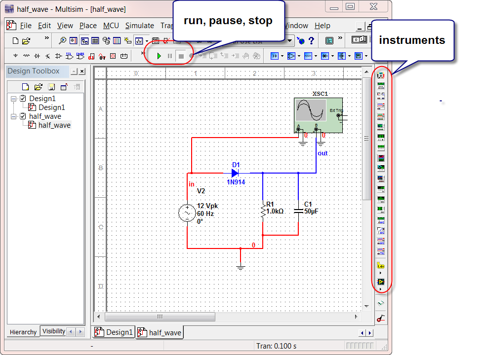
Download this multisim design file for half wave rectifier. Open it up in Multisim:
Note that the scope is an “instrument” you can drag from the instrument toolbar. Run the simulation by pressing the run button.
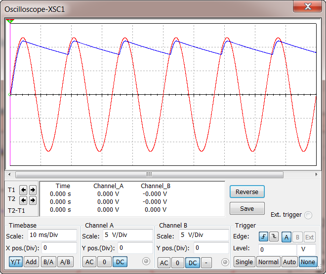
Pause or stop the simulation to examine the output. Double click the scope to see its display:
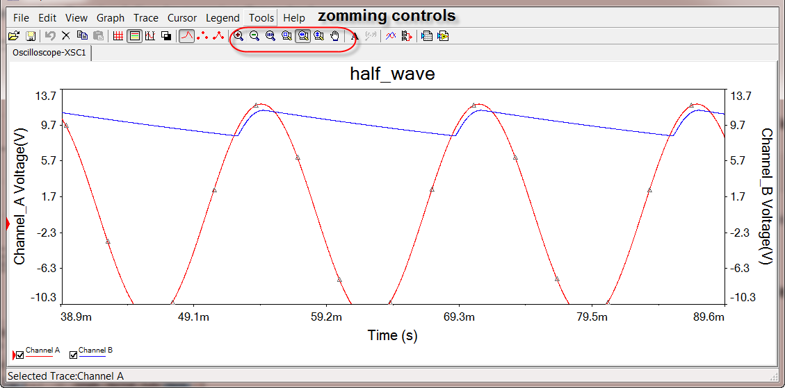
Use view -> grapher for more flexibility in controlling the looks of the waveforms.
Change the value of the capacitor, re-run simulation, observe how the ripple voltage changes. Think about why.
An extreme case is to just remove the capacitor, try that as well, see if you can associate the results with the theories learned in class.
Open a new design and reproduce the whole design on your own.
3.4. Full Wave Diode Bridge
Download this multisim design file for full wave diode bridge rectifier. Run the simulation by pressing the run button.
Observe the output.
Add another scope to measure the reverse voltage across diode D4. Think about at what time point in a cycle the diode D4 sees PIV.
Repeat this for all other diodes.
Try sketching the input and output waveforms by hand without looking at the Multisim simulation results.
Modify your circuit so that you get a negative power supply.
3.5. Parametric Sweep
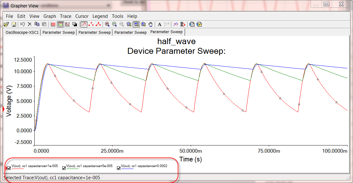
We know that varying the capacitance affects the output of the circuit. Naturally we would like to examine circuit waveforms for different capacitance values. The instruments way of simulation, however, does not support parametric sweep.
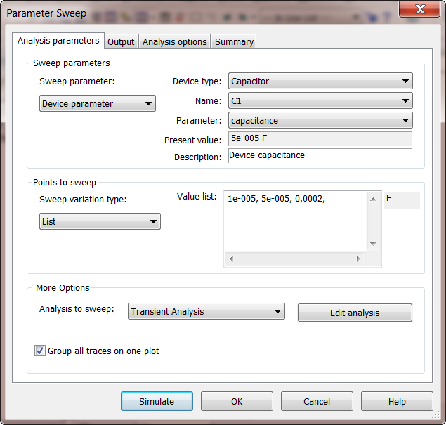
To do parametric sweep, go to Analyses -> Parameter Sweep, select Device Parameter for the Sweep Parameter option. Choose C1, input a list of values. Select Transient Analysis as the analysis to sweep, as shown below:
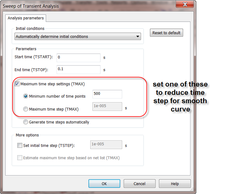
Click Edit Analysis so that you can set the parameters of the transient analysis. This includes TSTOP, the stopping time which needs to be at least several cycles to see meaningful waveforms, as well as the maximum time step or minimum number of points. The later is mainly used to obtain a smooth curve. Default time step control did not yield smooth waveforms.
Try using the default and changing these parameter, so you get a feel of how to choose these parameters in simulation.
You then simulate the design and get:
