Simulation of a Half-Wave Rectifier
Problem Statement (this is Prob. 3.91 in Jaeger, 3rd Ed.):
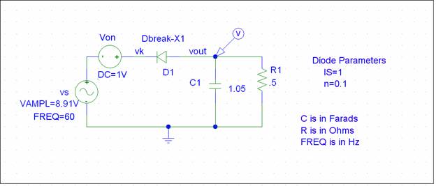
Negative ½-wave rectifier using an ideal diode, f= 60Hz, VRMS = 6.3 V, Vr = .25 V, R = 0.5 ohm, diode voltage drop is 1 V. Calculation yields C1 = 1.05 Farads.
_____________________________________________________________________________
In order to get the specified 1 V forward voltage drop across the diode, we will add a 1 V source in series with an ideal diode. This is known as the constant voltage drop model.
Experience has shown that a good model of the ideal diode (for this problem) is obtained by using the DBREAK model with IS = 1 and n = 0.1. (Eliminate Rs and Cjo from the default model statement.) Note that these values of IS and n are not physically realistic, but we are trying to model a physically unrealizable entity which has a zero volt forward drop.
We can set up the simulation as a transient analysis (results as a function of time).
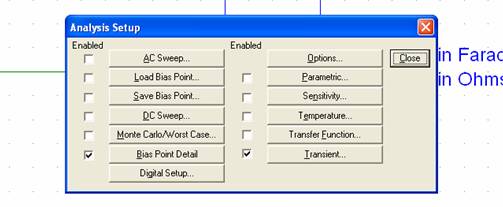
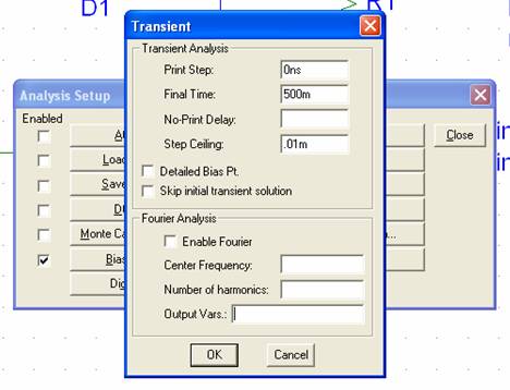
Note that the Transient box is checked. The parameters can be set in the Transient dialog box, as shown below. The Final Time is set to 500 ms and the Step Ceiling is set to 0.01 ms. Print Step is not used in this example, but it cannot be left blank, or an error message will result.
When this simulation is run, we get the following output waveform:
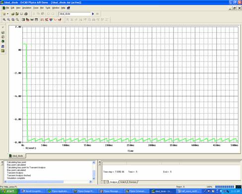
We can also look at the diode current:
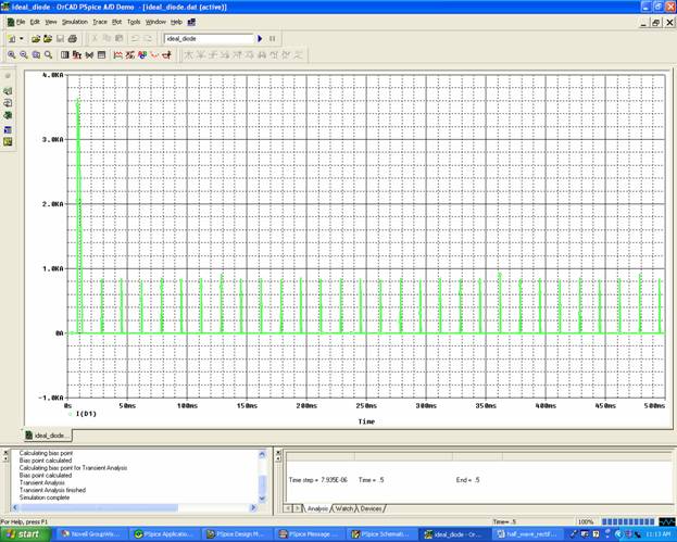
Closer inspection of these waveforms with PROBE's zoom and cursor functions yields ripple and peak diode current values that agree well with hand calculations.