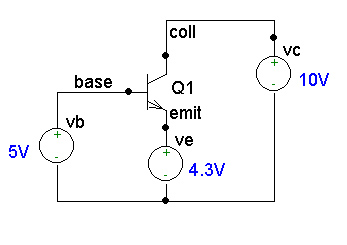
practice problem 1
*The npn BJT named Q1 is defined below:
Q1	coll	base	emit	nmod
.model	nmod	npn(is=1e-13A va=100V bf=100)
vc	coll	0	dc	10V
ve	emit	0	dc	4.3V
vb	base	0	dc	5V
.op
.options nopage
.end
Output File Components:
practice problem 1 *The npn BJT named Q1 is defined below: Q1 coll base emit nmod .model nmod npn(is=1e-13A va=100V bf=100) vc coll 0 dc 10V ve emit 0 dc 4.3V vb base 0 dc 5V .op .options nopage .end |
|
Notes on the input file:
(1) PSPICE regurgitates the input file listing, annotated with the time and date:
**** 02/04/97 22:07:32 *********** Evaluation PSpice (Jan 1993) **************

 practice problem 1


 ****     CIRCUIT DESCRIPTION


******************************************************************************


*The npn BJT named Q1 is defined below:
Q1      coll    base    emit    nmod
.model  nmod    npn(is=1e-13A va=100V bf=100)
vc      coll    0       dc      10V
ve      emit    0       dc      4.3V
vb      base    0       dc      5V
.op
.options nopage
.end
**** BJT MODEL PARAMETERS
(2) Here are the values for the device models parameters used in the circuit. Some of these are obtained from the model statement(s) in the input file, others are calculated or default values. These parameters are described in most PSPICE reference books.
               nmod
               NPN
          IS  100.000000E-15
          BF  100
          NF    1
         VAF  100
          BR    1
          NR    1
**** SMALL SIGNAL BIAS SOLUTION TEMPERATURE = 27.000 DEG C
(3) This section lists the dc voltage at each node in the circuit. Also note that the default temperature is 27 C = 300.15 K. When performing hand calculations of junction currents using exponentials, e.g., IC = IS(exp(VBE/VT), in order for your results to agree with PSPICE it might be necessary to use a value for the thermal voltage calculated with high precision. For T = 27 C, VT = kT/q = 25.87 mV. The temperature can be set to any value by including a .TEMP statement in the input file. Also, the analysis can be repeated at a sequence of temperatures (see PSPICE reference).
 NODE   VOLTAGE     NODE   VOLTAGE     NODE   VOLTAGE     NODE   VOLTAGE


( base)    5.0000  ( coll)   10.0000  ( emit)    4.3000
(4) The following section lists each voltage source by name, together with the dc current flowing through it. The convention is that positive current flows into the + node of the source, through the source, and leaves the - node. Thus, if the voltage source value is positive and the current is negative, then power is being delivered by the source.
    VOLTAGE SOURCE CURRENTS
    NAME         CURRENT

    vc          -5.958E-02
    ve           6.015E-02
    vb          -5.675E-04
(5) The next line gives the total power dissipation in the circuit.
TOTAL POWER DISSIPATION 3.40E-01 WATTS
**** OPERATING POINT INFORMATION TEMPERATURE = 27.000 DEG C
(6) This section provides detailed information about the solid state devices as requested by including the '.op' statement in the input file.
**** BIPOLAR JUNCTION TRANSISTORS
NAME         Q1
MODEL        nmod
IB	5.67E-04	...This shows a dc current of 0.567 mA flowing into the base
IC	5.96E-02 	...This shows 59.6 mA flowing into the collector
VBE    	7.00E-01	...B-E junction is forward-biased
VBC   	 -5.00E+00	...C-B junction is reverse-biased (n-type coll. higher than p-type base)
VCE	5.70E+00	      ...These junction conditions indicate forward active operating region.
BETADC	1.05E+02
GM	2.30E+00
RPI	4.56E+01
RX	0.00E+00
RO	1.76E+03
CBE	0.00E+00
CBC	0.00E+00
CBX	0.00E+00
CJS	0.00E+00
BETAAC	1.05E+02
FT	3.67E+19
JOB CONCLUDED
(7) The last section prints CPU statistics. More detail can be requested by specifying various parameters in the '.options' statement.
TOTAL JOB TIME .55
Top of Page