12. I-V Measurement Automation Using Signal Express
12.1. Goal
- Introduction to SignalExpress and automated measurement
- Invert a voltage with an OPAMP
- Measure I-V characteristics of both NMOS and PMOS
- Continue to develop professional lab skills and written communication skills.
12.2. Required Components
- ALD1105PBL Package
- Dual Voltage Inverter Package
12.3. Required Software
- SignalExpress
12.4. Overview
In this experiment, we will build our own MOSFET curve tracer with the variable power supply (VPS) and the DMM used as a current meter. We have made similar measurements before using a customized Labview program I wrote. An alternative or compromise between taking manual measurements and customized Labview programming is to use Signal Express, an interactive data-logging software that is designed to automate the measurement process, particularly with devics from NI, like the ELVIS II+ boards we use.
The basic requirement of I-V curve tracing is that we need to vary two voltage sources, and measure currents. For MOSFETs, we have just one current to measure, the drain current. We can use DMM.
We also need to vary both the gate voltage and drain voltage. Even though we have two variable power supplies, we cannot use them as is for curve tracing. The reason is that one outputs positive voltage, VPS+, and the other outputs negative voltage, VPS-.
To get around this problem, we have made a dual channel voltage inverter using a dual channel opamp. It is a package you can insert onto a breadboard. Internally, the opamp is configured to invert an input voltage. It is dual channel, meaning it can invert two voltages. We will connect VPS+ and VPS- to the two inputs. At the outputs, we have -VPS+ and -VPS-, the negated inputs.
For NMOSFETs, VGS and VDS are typically positive. We will use VPS+ and -VPS-. For PMOSFETs, VGS and VDS are typically negative. We will use VPS- and -VPS+.
12.4.1. Transistors Used
The MOSFETs we will use in this experiment are from ALD1105, an IC containing two n-MOSFETs and two p-MOSFETs. A circuit symbol description of the two pairs of transistors from the data sheet is shown below in figure 1.

Figure 1: Circuit Symbol and Pin Numbers for the Pairs of N-channel and P-channel MOSFETs.
Note each transistor has four terminals: drain (D), source (S), gate (G), and substrate, which is called body (B) in our text. As we learned in class, all the n-MOSFETs on an IC share the same p-type body, which needs to be tied to the lowest voltage in a system to keep all the source/drain to body PN junctions zero or reverse biased.
Similarly, all the p-MOSFETs on an IC share the same n-type body, which needs to be tied to the highest voltage in a system to keep all the source/drain to body PN junctions zero or reverse biased.
The pin diagram seen in figure 2 shows the package layout and various pin connections for ALD1105.

Figure 2: Pin diagram of ALD1105 package.
12.5. Pre-Lab
- Obtain the data sheet for the ALD1105 from:
- Using the data sheet, determine the values of the threshold voltage range, the maximum continuous drain current ID, the maximum drain-source voltage, and the maximum allowed power dissipation, Ptot.
- Draw a pin-level wiring diagram of a CMOS inverter. Use the pair of NMOS and PMOS gates on the right side of the ALD1105 IC.
12.6. Lab Exercise
There are 4 parts. Have your GTA sign off on each part before proceeding to the next part.
12.6.1. Single Measurement
In this section SignalExpress will be introduced and a single simple measurement of an NMOS transistor will be done.
Proceed as follows:
- Obtain a ALD1105 IC. Using the data sheet as a guide, identify the drain, gate, and source terminals of the NMOS transistor using Pins 1-4.
- Power off ELVIS II board.
- Connect the voltage inverter terminal in the following way.
- +15 is connected to the +15 V
- -15 is connected to the -15 V
- GND is connected to ground
- IN1 is connected to VPS-
- Connect the VPS+ to the Drain, connect the VPS- to the voltage inverter terminal IN1, connect the voltage inverter terminal OUT1 to the Gate, connect the substrate and source to ground.
- Connect the DMM in such a way as to measure Id.
- Your circuit should look like figure 3.
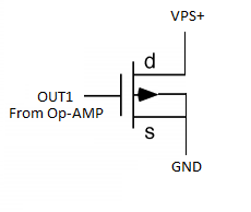
Figure 3: Diagram of Circuit.
- Open SignalExpress, click Add Step in the top-left hand corner and select NI Elvismx Variable Power Supply under NI Elvismx > Analog > Generate Signals.
- Change the VPS- and VPS+ to -5V and +10V respectively.
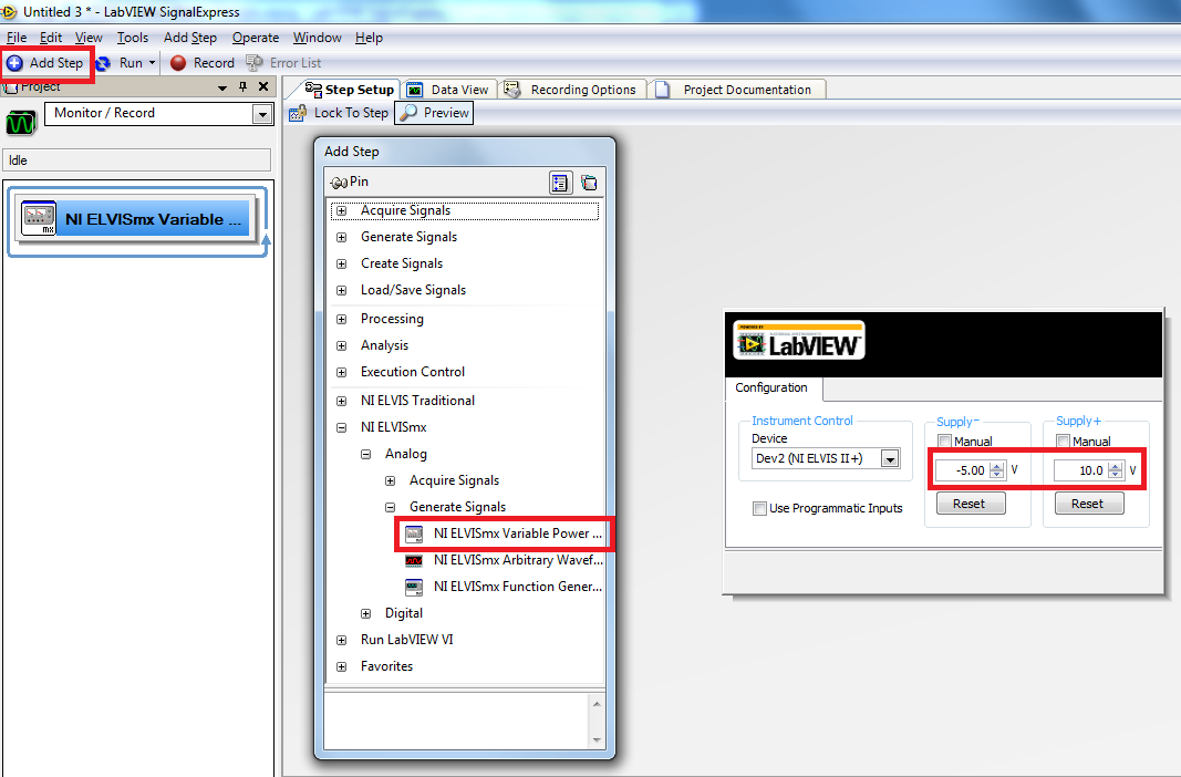
Figure 4: Configuring VPS SignalExpress.
- Click the Add Step again, but this time select Acquire Signals instead of Generate and select the DMM. Once this screen is open you will change the measurement function to DC Current.
- Power on the ELVIS II board and select Run Once in the top-left corner. You should have something similar to figure 5.
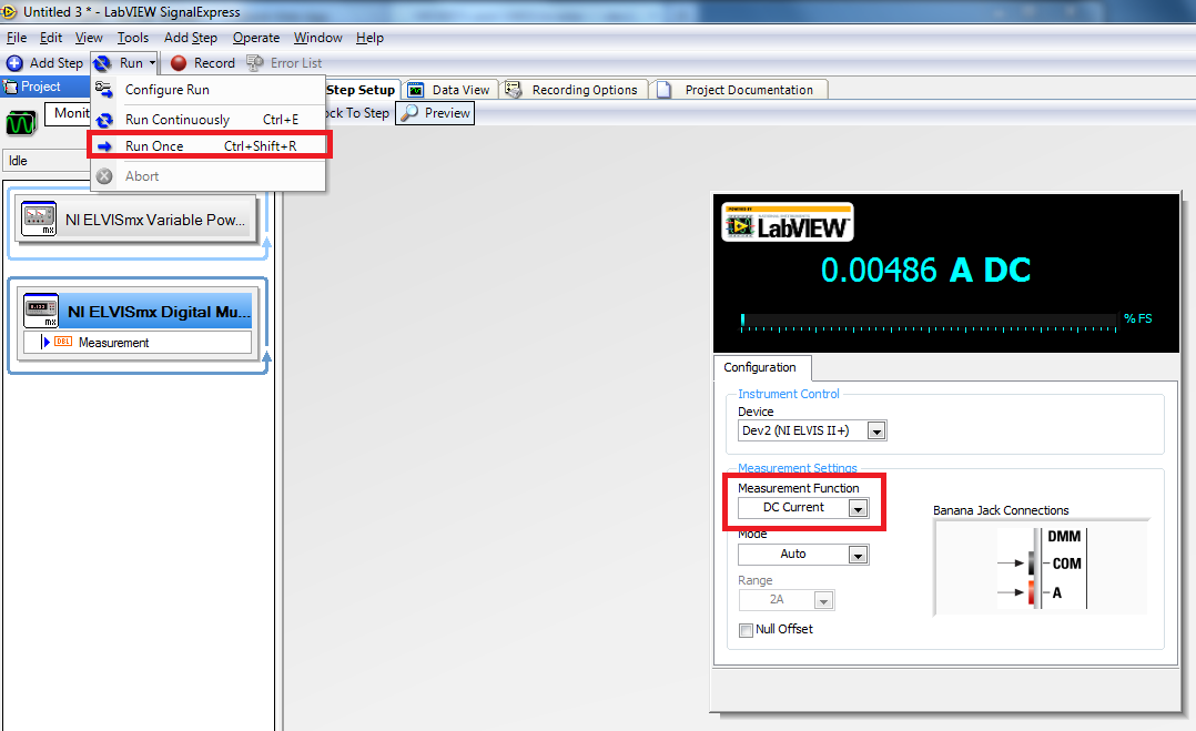
Configuring DMM in SignalExpress.
Repeat this measurement for when the transistor is in the liner region (determine from prelab what to set the drain voltage to). Change the VPS- to -3V and -8V and repeat these measurements. Remember that the VPS- is actually being inverted by the voltage inverter terminal.
12.6.2. SignalExpress Sweep
In this section a range of voltages will be swept and measured in order to produce a Id-Vg curve. For now we will leave the circuit constructed how it is and merely change SignalExpress.
Proceed as follows:
- Power off ELVIS II board.
- Click the Add Step button once again, this time select Sweep, under Execution Control.
- Click and drag the previous two bubbles into the sweep, making sure that the Variable Power Supply is before the DMM.
- Make sure to set the VPS- back to -5V.
- Click on Sweep. Select Add under Sweep Configuration and select the VPS+. This is where we will sweep Vd. Change the settings such that it will sweep from 0 to 10 V with 20 points.
- Under Sweep Output click add. Select the DMM masurement option. This will allow you to output the results of the sweep measurement.
- Your setup should look like figure 6.
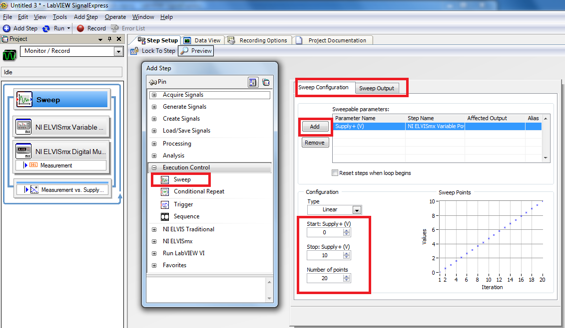
Figure 6: Sweep Configuration.
- Power on the ELVIS II board.
- Now click Run Once. Select the Data View tab from the top-middle of the screen and then click and drag the Measurement vs. Supply step onto it. This should produce a graph similar to figure 7.
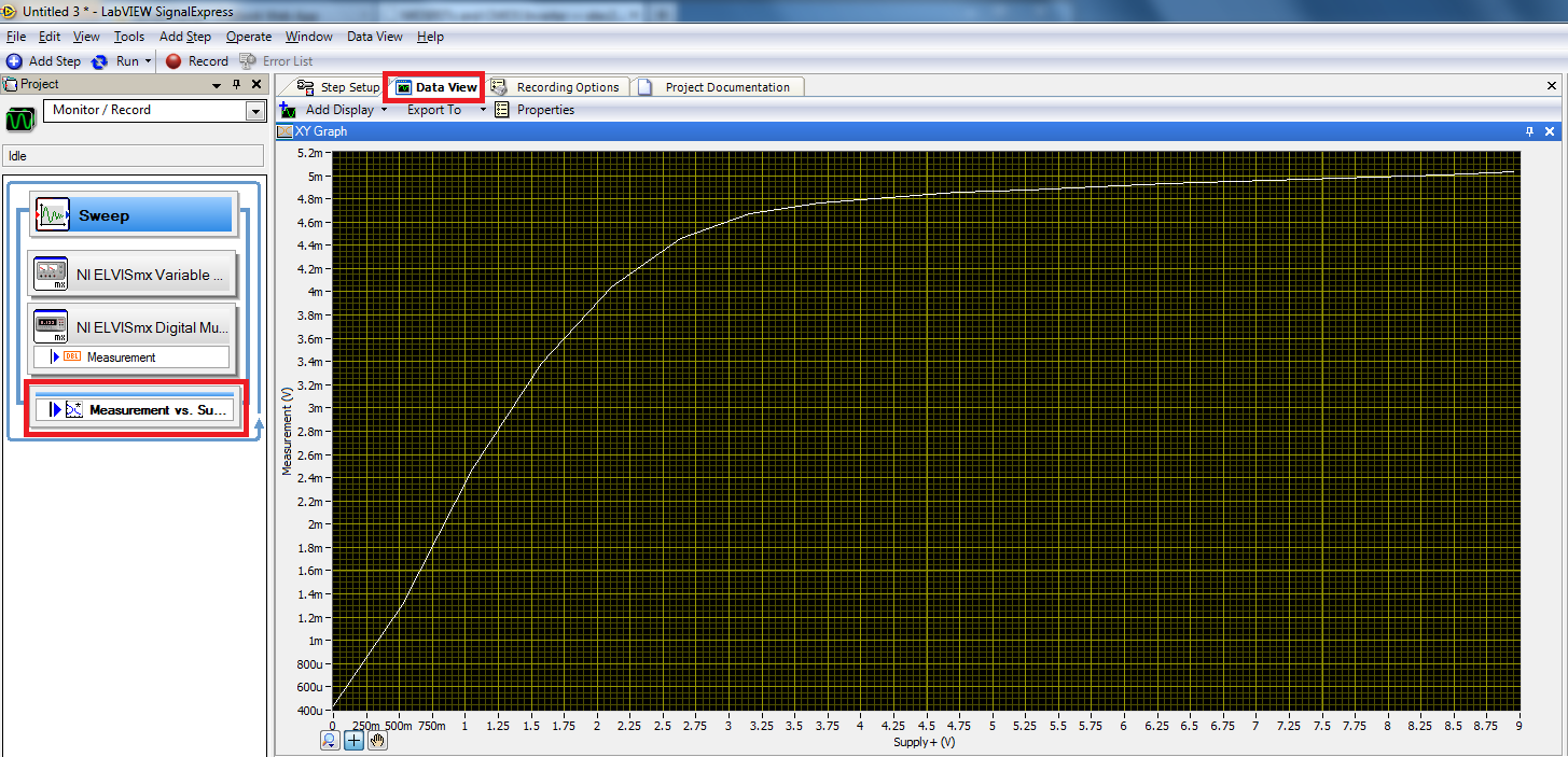
Figure 7: Sweep Output.
It is important to remember that the y-axis is not labelled properly. Under Sweep Output there is an Output Option that allows you to change the label. Do this now, you should enter Id (mA) in there now.
Now configure SignalExpress in order to sweep a larger number of points, 40 for example. Take a screenshot. Now configure SignalExpress to perform this sweep again using -3V and -8V. Take screenshots.
12.6.3. NMOS Family of Id-Vg Curves
In this step we will generate a family of curves for the NMOS transistor we are using.
Proceed as follows:
- Power off ELVIS II board.
- Click the Add Step button once again. Select Sweep once again but this time place all previous steps within this new sweep.
- Click on Sweep. Select Add under Sweep Configuration and select the VPS-. This is where we will sweep Vg. Change the settings such that it will sweep from -2 to -8 in 4 points. This will allow us to create a curve much like we did in the last step, but over multiple gate voltages.
- Under Sweep output you should add the Measurement vs Supply and make sure to change your labels.
- Right-click on the VPS step and select Set Run Delay. Then set the Post Run Delay to 500ms. Similarly, set the pre Run Delay of the DMM to 500ms. This is done in order to allow the ELVIS board time to stabilize before it makes a measurement.
- Power on the ELVIS II board, your program should look similar to the screenshot in figure 8 before running it.
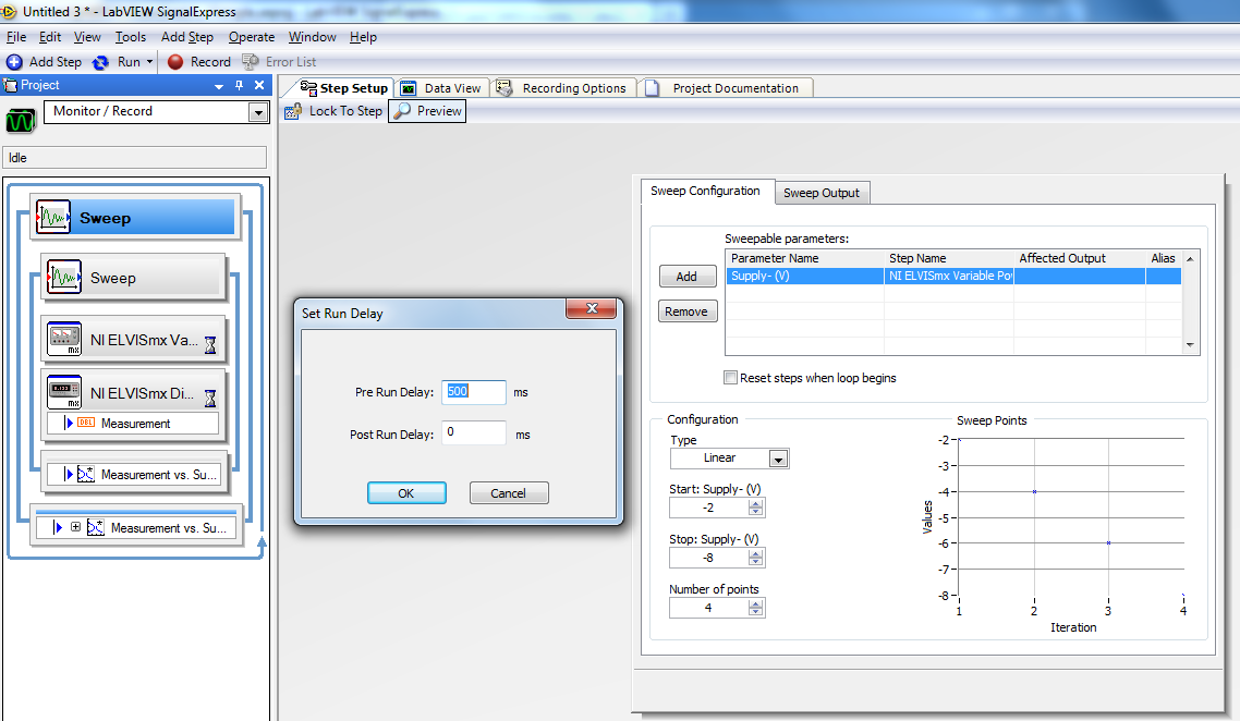
Figure 8: Nested Sweep Configuration.
- Click Run Once and drag the outer Measurement vs Supply to the Data View. You should have something that looks similar to the screenshot in figure 9.

Figure 9: Nested Sweep Output.
12.6.4. PMOS Family of Id-Vg Curves
In this step we will now test a PMOS transistor. This can easily be achieved by changing the biasing and connecting the leads to the PMOS portion of the ALD1105.
Proceed as follows:
- Power off ELVIS II board.
- Connect the voltage inverter terminal as following:
- +15 is connected to the +15 V
- -15 is connected to the -15 V
- GND is connected to ground
- IN1 is connected to VPS+
- Connect the VPS- to the Drain, connect the VPS+ to the voltage inverter terminal IN1, connect the voltage inverter terminal OUT1 to the Gate, connect the substrate and source to ground.
- Connect the DMM in such a way as to measure Id.
- Your circuit should look like the diagram in figure 10.
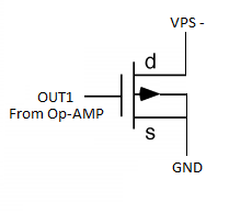
Figure 10: Diagram of Circuit.
- SignalExpress now needs a few minor changes.
- In the inner Sweep Step Setup Supply+ needs to be changed to Supply- with the voltages being negate.
- In the outer Sweep Step Setup Supply- needs to be changed to Supply+ with the voltages being positive.
- The screenshot in figure 11 will provide details.
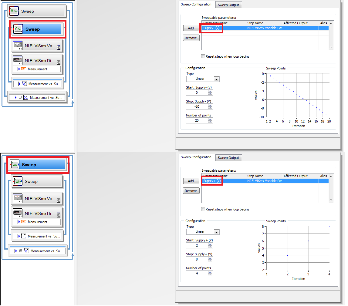
Figure 11: Nested Sweep Configuration.
- Power on the ELVIS II board.
- Click Run Once and drag the outer Measurement vs Supply to the Data View. You should have something that looks similar to the screenshot in figure 12.

Figure 12: Nested Sweep Output.
It is important to notice that the curve appears backwards. This is a result of the SignalExpress settings we changed earlier and should be read from 0V on the right to the -10V on the left.